


Cyber-Physical Systems are cyber systems controlling physical entities, these entities being, for instance, mechanical or biological. Their development involves different engineering disciplines that use different models, written in languages with different semantics. These heterogeneous models are participating in the dynamic of the system and a coupled simulation of these models can be used to understand the system behavior.
The Functional Mock-up Interface is a standard for co-simulation that provides a time-driven API to communicate between the solvers of different models. At runtime, data can then be exchanged between the different models to represent the interaction between the models.
Overview
This page provides an overview of the steps to launch the experiments using the FMI extensions proposed. The user will require downloading the source code and follow the steps describe in part 1 and 2.
Supported architecture: Linux x86_64 (Tested on Ubuntu 16.04 and Fedora 23)
Part 1: Download and compile source code
First, download the source code (.tar.gz) from here .
To compile the source code, all these dependencies must be satisfied:
- g++
- cmake
- libgfortran-4.8-dev
- libexpat1-dev
- libxml2-dev
Then, in the terminal:
$ mkdir build
$ cd build
$ cmake ..
$ make
Each test case has two implementations: one using the FIDEL APIs and one using the current API (v2.0).
At the end of each simulation, a .csv file and a .png file are created. In these files, there are the results of the simulation.
Part 2: Case Study and Experimental results
Case 1: Wheel encoder driver
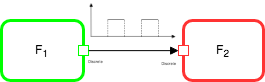
The first use case is a system composed by a wheel encoder driver FMU and a speed computation FMU. It is used to describe the fmi2SimulateUntilDiscontinuity API and run benchmarks on it.
To compile and run it, run in the terminal:
$ make sim_wheel_encoder_fidel
$ cd bin
$ ./sim_wheel_encoder_fidel
Results
Case 2: Sensor and environment
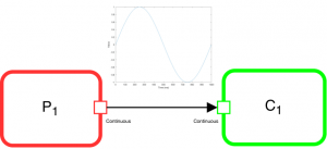
The figure shows how the two FMUs are linked together. The graph shows the signal that transit from the environment FMU to the sensor FMU.
To build and execute the example, launch these command:
$ make sim_sensor_env_fidel
$ cd bin
$ ./sim_sensor_env_fidel
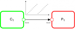
Case 3: Modulo counter
This case represents a modulo counter.
$ make sim_modulo_counter_fidel_conditional
$ cd bin
$ ./sim_modulo_counter_fidel_conditional