
The 60GHz downconverter architecture is presented on the Figure 1.
The 60GHz is composed of three parts:
- The antenna array of primary source
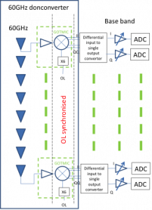
Figure 1: 60GHz downconverter architecture
- The downconversion 60GHz- FI
- The LO (Local Oscillator) distribution to ensure the synchronisation
I. The antenna array of primary source
Two topologies have been studied:
- DRA (Dielectric Resonator Antenna) with LTCC technology
- 2X2 patch array antenna with PCB technology
a) LTCC 60GHz DRA antenna
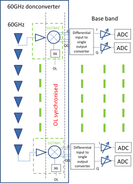
The LTCC technology is adapted to the integration of millimeterwave system . In this way, the design of an antenna has been designed. DRA antenna is a good candidate for millimeterwave antenna for several reasons:
- Good efficiency
- Wide frequency band
- Compatible with LTCC technology
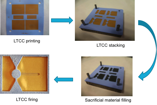 Figure 2: LTCC process |
 Figure 3: DRA antenna S11 measurement |
Figure 4: DRA radiation pattern
The performances are:
- Full half power beamwidth in H-plane 40°
- Maximum gain of 7 dBi at 60 GHz
b) 2X2 patch array antenna
To limit the risk of components integration, PCB technology is chosen for the first prototype. The final goal is to ensure the co-integration in order to minimize the interconnection losses. Then a patch array antenna has been designed on the same substrate than the downconverter.
The specification is based on an optimization of the illumination of the transmitarray antenna:
- Full half power beamwidth in H-plane 48.2°
- Gain of 8.1 dBi at 60 GHz
- 1dB maximum ondulation over 6 GHz (10% fractional bandwidth)
 Figure 5: 2X2 patch array antenna |
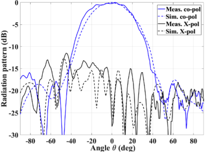 Figure 6: Radiation pattern measurement of the 2×2 patch array antenna |
c) 8 linear patch arrays for the primary source
Due to the high risks concerning the integration and interconnection of the MMIC chip with wire bonding, for the first prototype the antenna array and the downconverter are interconnected by a short coaxial cable.
In the project, the array of primary source should be interconnected to the 60GHz down converter for channel sounding application or to the B-COM platform for multi-users transmission.
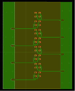
Figure 7: Layout of 8 primary sources antennas
II. 60GHz-FI Downconversion part
The downconversion is based on a commercial chip MMIC provided by GOTMIC. Due to the distance between input antenna imposed by the array antenna, the integration of the chip is a technological challenge with several constraints:
- Small place available
- Minimisation of the losses at 60 GHz
- Several technics of components report used : Bonding, soldering
- Need of several voltage supplies

Figure 8: MMIC assembly at Lab-STICC (IMT Altantique)

Figure 9: First prototype

Figure 10: Schematic diagram of the 60GHz-FI Down-conversion test bench
The measurement results are presented on the Figure 11.

Figure 11: Output power in FI band
The 8 RF downconverters are integrated on a support.
Figure 12: the 8 RF downconverter
III. LO distribution for synchronisation
A PCB circuit has been design to distribute the same local oscillator signal for the 8 downconverter. The LO is generated from a Analog devices card with a tuning voltage of the frequency to fix the FI frequency depending on the equipment used (Vector Network Analyser, channel sounder…).

Figure 13: LO distribution circuit for synchronisation