
For the sake of simplicity, the geometrical calculations are presented in 1D. For the complete 2D demonstration, further information is available in the Corien Prins thesis “Inverse Methods for Illumination Optics” here.
The first step of this demonstration consists in finding the differential equation for a reflector surface which transform a parallel beam of light into a given output intensity distribution.
In the second step, we find the relation between the illuminance of a target plane in the far field and the corresponding intensity distribution.
- Problem Configuration
- The Reflector Equation
- Target Plane
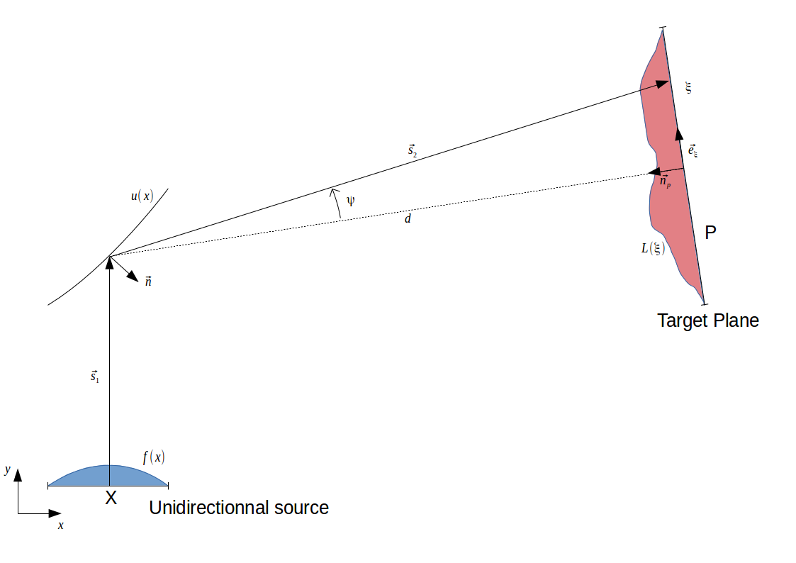
\(\displaystyle f(x)\), \(\displaystyle L(\xi)\), and the target plane position being known, the problem can be summarized as follow:
Find the shape \(\displaystyle u(x)\) which transforms the unidirectionnal beam of light with an intensity \(\displaystyle f(x)\) into an illuminance \(\displaystyle L(\xi)\) on the target plane. This target plane is located at a large distance from the reflector which means that this latter is a point compared to the target plane dimensions.
The following notations will used throughout this page:
\(\displaystyle p = \frac{du}{dx}\) and \(\displaystyle \hat{n}\) for a unit vector.
In this part, we will derive the equation which links the reflector shape u(x) to the parallel beam of source light and to a specified output intensity distribution in the far field.
The 1D source intensity is along the x-axis and emits in the direction \(\displaystyle \vec{s_1} = \begin{pmatrix} 1\\0 \end{pmatrix}\). The coordinates system is chosen such that the reflector is close to the origin and we assume that the reflector size is negligible (the reflector is a point) compared to the observation distance of the reflected rays.
We denote \(\displaystyle G(\psi)\) the target output intensity in the direction of angle \(\displaystyle \psi\).
– Let’s start with the luminous flux \(\displaystyle d\Phi\) emitted by an infinitesimal segment \(\displaystyle dx\):
\(\displaystyle d\Phi=f(x)dx\)
This flux is reflected through an infinitesimal segment on the unit circle which dimension is \(\displaystyle \frac{d\hat{s_2}}{dx}dx\)
Flux conservation then gives us:
\(\displaystyle G(\psi)|\frac{d\hat{s_2}}{dx}|=f(x)\)
– We now have to calculate the derivative. The vectorial reflection law is the following:
\(\displaystyle \hat{s_2}=\hat{s_1}-2(\hat{s_1}\cdot\hat{n})\hat{n}\), with \(\displaystyle \hat{n}=\frac{\vec{n}}{|\vec{n}|}\) and \(\displaystyle \vec{n}=\begin{pmatrix} p\\-1 \end{pmatrix}\)
\(\displaystyle \Rightarrow \hat{s_2}=\frac{1}{p^2+1}\begin{pmatrix} 2p\\p^2-1 \end{pmatrix}\)
\(\displaystyle \frac{d\hat{s_2}}{dx}=\frac{2\frac{dp}{dx}}{(p^2+1)^2}\begin{pmatrix} -p^2+1\\2p \end{pmatrix}\)
\(\displaystyle \Rightarrow |\frac{d\hat{s_2}}{dx}|=\frac{2\frac{dp}{dx}}{p^2+1}\)
Replacing the derivative’s norm into the flux conservation gives us this differential equation:
\(\displaystyle \frac{d^2u}{dx}=\frac{f(x)(p^2+1)}{2G(\psi)}\)
This equation contains the variable \(\displaystyle \psi \) but we need a dependence in \(\displaystyle p \). Noticing that:
\(\displaystyle \hat{s_2}=\begin{pmatrix} \cos(\psi)\\\sin(\psi) \end{pmatrix}=\frac{1}{p^2+1}\begin{pmatrix} 2p\\p^2-1 \end{pmatrix} \Leftrightarrow \psi=\left \{
\begin{array}{r c l}
+\arccos(\frac{2p}{p^2+1}) & p > 1 \\
-\arccos(\frac{2p}{p^2+1}) & 0 \leq p \leq 1
\end{array}
\right .\),
we can now define a new function \(\displaystyle \tilde{G} \) depending on \(\displaystyle p \) instead of \(\displaystyle \psi \) and we finally obtain this differential equation:
\(\displaystyle \frac{d^2u}{dx}=\frac{f(x)(p^2+1)}{2\tilde{G}(p)} \Leftrightarrow det(D^2u)=\frac{f(x)}{g(\nabla(u))}\)
which is of Monge-Ampere type.
Most of the time, \(\displaystyle \tilde{G}(p) \) is not directly prescribed, and we only dispose of \(\displaystyle L(\xi) \), the target plane illuminance. To still use the previously derived Monge-Ampere equation, we need to find the intensity distribution function \(\displaystyle \tilde{G} \) that would produce a given target illuminance \(\displaystyle L \).
– To do this we use the flux conservation through an infinitesimal segment of the target plane and and its projection on the unit circle. This gives us:
\(\displaystyle \tilde{G}(p)d\psi=L(\xi)d\xi \)
\(\displaystyle \Leftrightarrow \tilde{G}(p)=\frac{d\xi}{d\psi}L(\xi) \)
On one hand, we dispose of the following relation between \(\displaystyle \xi \) and \(\displaystyle \psi \):
\(\displaystyle \xi=d\tan(\psi) \)
\(\displaystyle \Rightarrow \tilde{G}(p)=\frac{d}{\cos^2(\psi)}L(\xi) \)
And on another hand we know that:
\(\displaystyle \cos(\psi)=d\sqrt{\xi^2+d^2} \)
\(\displaystyle \Rightarrow \tilde{G}(p)=\frac{\xi^2+d^2}{d}L(\xi) \)
– To close the loop, we need \(\displaystyle \xi \) as a function of \(\displaystyle p \). We know firstly that \(\displaystyle \hat{s_2} \) intersects the target plane if:
\(\displaystyle \hat{s_2}=\frac{\xi\hat{e_\xi}-d\hat{n_p}}{\sqrt{\xi^2+d^2}} \)
After scalar products by \(\displaystyle \hat{e_\xi} \) and \(\displaystyle \hat{n_p} \), we obtain this relation:
\(\displaystyle \xi=-d\frac{\hat{s_2} \cdot \hat{e_\xi}}{\hat{s_2} \cdot \hat{n_p}} \)
Thanks to the expression of \(\displaystyle \hat{s_2}(p) \) shown in the reflector equation part, we have \(\displaystyle \xi(p) \)