
Fig. 1 shows the set-up schematic to characterize beam switching and the links. It enables radiation pattern measurements along a vertical cut. The photonic generation module hosts the blocks used for mm-wave generation by photomixing: two fiber-coupled free-running laser diodes (Toptica Photonics DFB pro BFY), a fiber combiner, a Mach Zhender modulator (iXBlue MX-LN-20) with its driver (iXBlue DR-DG-20-MO), a modulation bias controller that sets the modulator at the quadrature point (iXBlue MBC-DG-LAB), and a polarization controller. The photonic generation module outputs two amplitude modulated, \( \approx 1.55\mu \)m optical tones whose separation is the desired mm-wave frequency. The module input is an RF signal that modulates the output beatnote.
Next, the module output is directed by a fiber patchcord to a lensed fiber (OZ optics) that illuminates one of the two UTC-PDs in the chip. At a distance corresponding to bfl from the antenna, the lens is placed and aligned with another positioner. The receiving side consists of a WR-10 horn +lens, in turn connected to a zero bias Schottky barrier diode detector (ZSBD) from VDI. The ZSBD is mounted on a linear motorized translation stage (Thorlabs LTS300), which enables a 30 cm excursion range. At the output of the ZSBD, a 42 dB gain amplifier (Wenteq ABL0300004030) plus a 10 dB gain block (Minicircuits ZX60-14012L-S+) are connected. Finally, the lock-in detector is replaced by an Anritsu MP1763C pulse pattern generator providing the RF input to the photonic generation module of Fig. 9a, and an Anritsu 1764C error detector. To avoid undesired reflections and standing waves, the optical table, translation stage, and receiving module are covered with absorber.
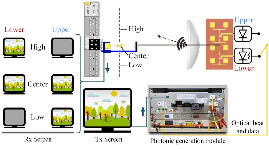
Fig. 1: Scheme of the laboratory set-up for photonic-enabled beam switching transmission.
Fig. 2(a) shows the bit-error rate (BER) versus the detector elevation angle when the upper or lower sub-arrays are active for a carrier at the lower frequency window in the E-band (73 GHz). In turn, Fig.2(b) depicts the same curve for a carrier in the higher frequency window (83 GHz). Fig. 11c shows the eye diagram for optimum BER = 10^(-11). The photocurrent is kept at 3.7 mA and the link distance is d = 60.5 cm. On-off keying modulation is used with a data rate of 5 Gbps, which is limited by the amplifier bandwidth (3 GHz). The curves in Figs. 2(a) and (b) show that, for both E-band windows, link operation is accomplished (BER < 10^(-3)) over an angular range approximately twice as wide with respect to a fixed beam. Thus, the transmitter yields a system more tolerant to misalignment.
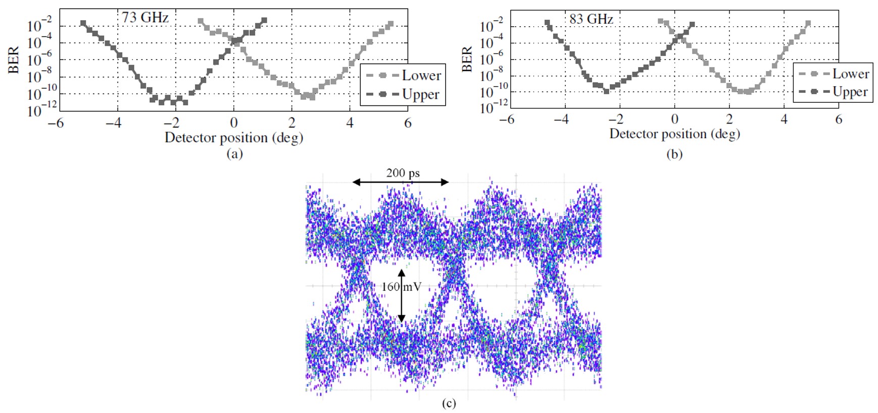
Fig. 2: (a) and (b): BER versus detector elevation angle for the upper and lower sub-arrays at the two windows of the E-band. (c) Eye diagram for BER= 10^(-11) with a 73 GHz carrier.
In collaboration with UC3M partners, we have also explored real-time transmission of 4K video. In the video below, one can appreciate how transmission is interrupted when we block the beam trajectory with our hand.