
1 WP1 New light event readout board prototype
1.1 WP presentation
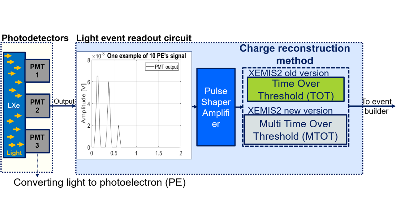
This task is about providing electric signals from VUV (Vacuum ultraviolet at 178 nm) generated during
scintillations within the liquid xenon (LXe). UV photons will be collected from off-the-shelf photodetectors. To detect low charges (few hundreds of pC), deposited on the photodetector by photoelectrons, and their timing, a self-triggered circuit is needed to collect and preprocess these data to ensure proper digital conversion. When scintillation happens, few photons reach the detector due to the LXe. Since the light emission is isotropic several detectors can output a signal. Hence, we have to discriminate correctly between low charges to select the detector receiving the most photons, i.e. the highest charge.
Typically, the photodetector output charge is converted into a time pulse whose duration is proportional
to the charge value, this technique is known as “Time Over Threshold” (TOT). Obtaining such a linear conversion is challenging for low charges yet essential to improve image SNR . The pulse duration is then digitized using an external clock. Finally, the external clock sets a time-window during which the photodetector could randomly fire several times, we must ensure that the charge to time conversion can be performed within the time window. Also, considering the number of disintegration expected, the data flow is also tremendous, about 1.106 pulses/s.
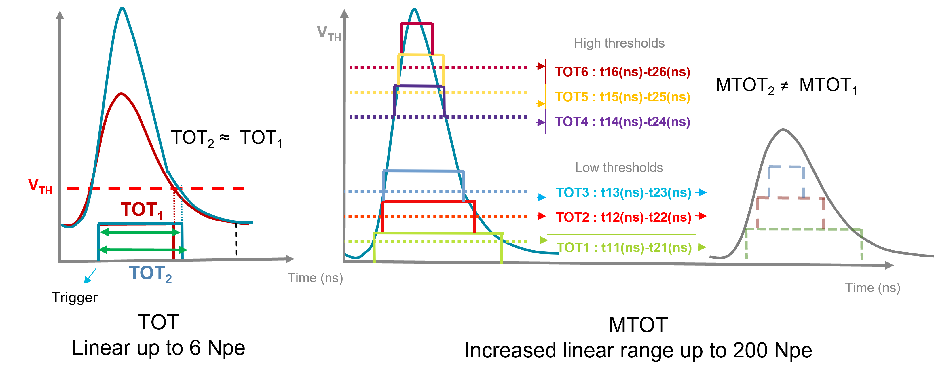
Time Over Threshold is not suited when counting a large number of photon is needed, i.e. more than 10 as shown in Fig. 1.2. As the number of PEs increasease, the resulting integration of the light pulses into a single analogue pulse by the shaper does not yield difference in the time varying digital signal steming from the threshold. Thus, this does not count the number of PEs above a dozen at best. A better solution to correctly count PEs above 10 is to generate several TOTs using several threshold voltages for the same analogue pulse and then add the TOTs up to get the corresponding number of PEs, Fig. 1.2.
1.2 Results
A new readout circuit implementing multi time-over-threshold has been designed, Fig. 1.3 shows the block diagram of the board. The PCB format is fully compatible with the XEMIS2 prototype, hence testing the prototype in real conditions is possible. Compared to the existing light readout circuit, this one has 6 differents digitally tunable (12 bits) threshold voltages, increased bandwidth for amplifiers and comparators resulting in better noise performance. Figure 1.4 shows a picture of the fabricated prototype, called XSREMTOT.
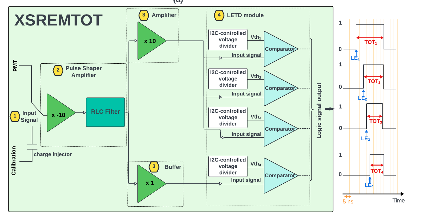
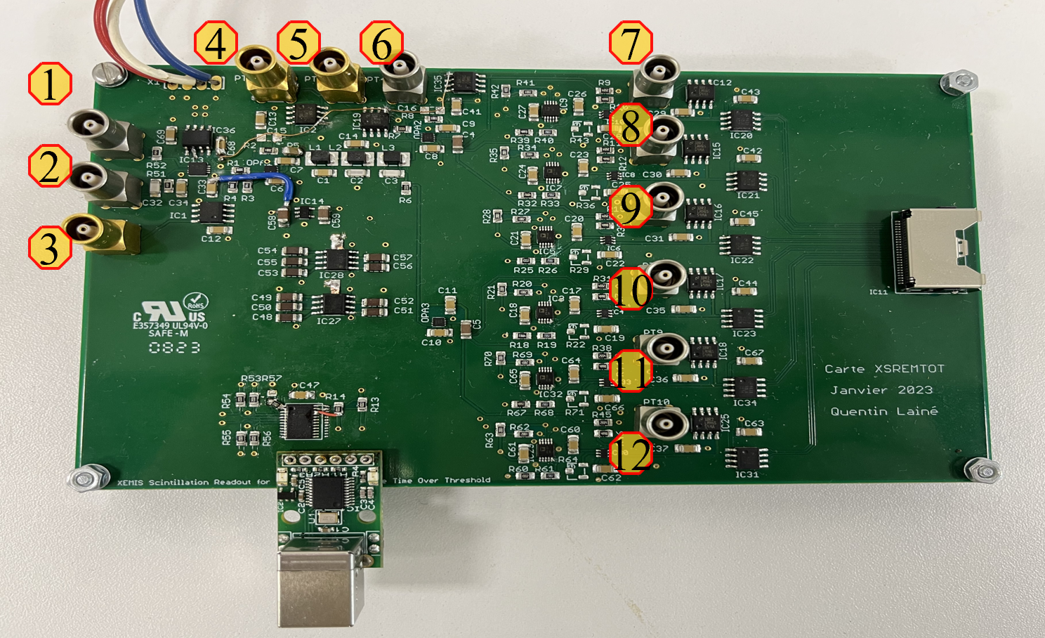
1-PMT input
2-Calibration input
3- Signal
4- Pre amp (x-10)
5- Filter output
6- Amplifier for low threshold (x10)
7 to 12 – ToT (logic signals)
A calibration protocol was carried out on a test bench to define the value of the four thresholds to reach a noise count rate of 1 kHz. The calibration set-up consists of a pulse generator, the XSREMTOT board, an FPGA, and a computer for data recording.
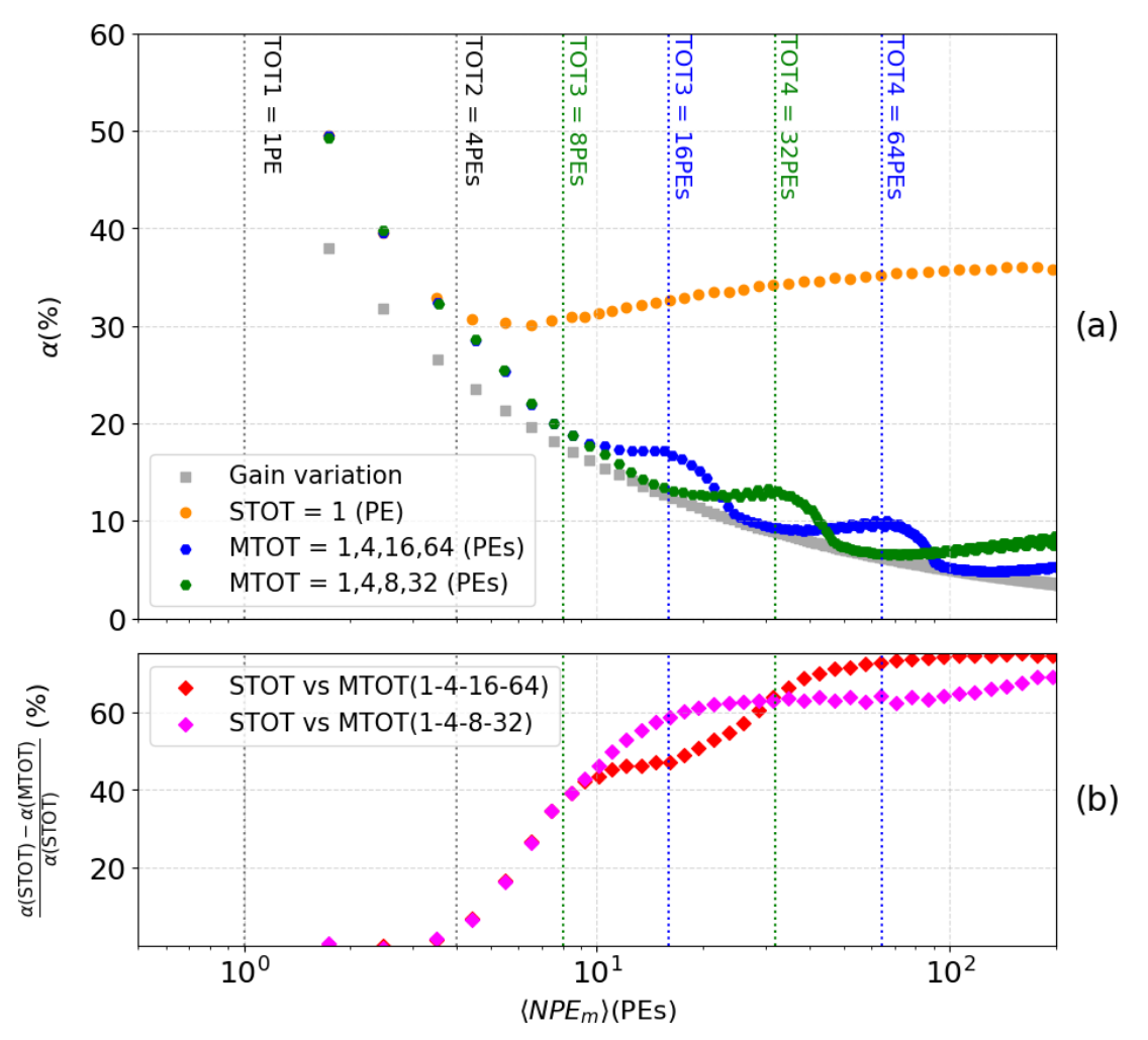
Figure 1.4a shows resolution of the MTOT method for two configurations of threshold levels, in blue for (1,4,16,64) PEs an in green for (1,4,8,32) PEs. These resolutions are compared with the one of the STOT method, as well (cf. orange vs blue or green dots in Figure 1.4a). The theoretical ideal resolution, depicted by gray squares, represents a scenario where the only perturbation is the unavoidable variation in PMT gain, while all other potential disturbances are absent. This comparison highlights the impact of these disturbances on the reconstruction accuracy. Figure 1.4b directly compares the two methods: STOT and MTOT. The relative difference between these methods is calculated for both sets of thresholds. This graph significantly highlights the precision improvement provided by MTOT. With each new threshold triggered (represented by blue and green dashed lines), the resolution of the number of NPEm increases dramatically, reaching up to 70% for the highest signals (>64 PEs) with the first set of thresholds within the studied range. It is important to note that the second set (magenta curve) offers better accuracy at the beginning of the interval studied, as its configuration is optimized for detecting smaller signals. The number of PEs detected in XEMIS2 depends on the activity of the radioactive source used. Accurate knowledge of the distribution of the vaccum UV photons across the XEMIS2 PMT network as a function of activity will enable maximizing efficiency by selecting the optimal threshold configuration for each injected dose.
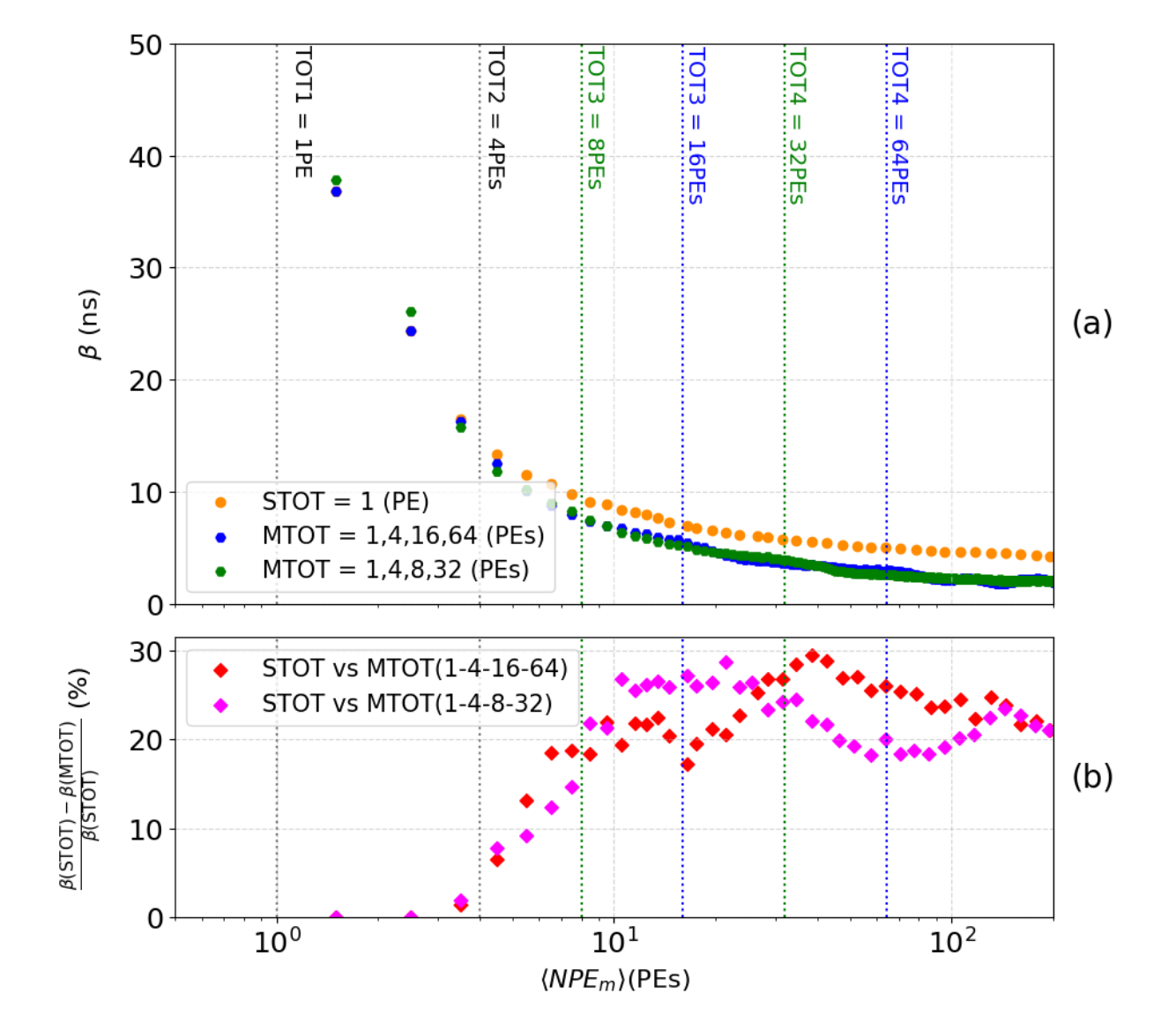
Another significant improvemen tbrought in by W1 is a 30% increase in the estimated event time represented by the leading edge (LE) time.
Figure 1.5 shows the standard deviation (represented by β) of the T0 distribution. Figure 1.5a compares the reconstruction of the initial time T0 using the STOT methods (yellow curve) and MTOT (blue curve for the set 1, 4, 16, and 64 PEs and green curve for the set 1, 4, 8, and 32 PEs) by plotting the parameter β as a function of NPEm. Figure 1.5b illustrates the relative difference between the two methods for both sets of thresholds, calculated as before. This visualization highlights the improvement in the precision of the reconstruction of the initial time T0 provided by the MTOT method. The correction of the walk provided by each threshold allows for an improvement of 20% to 30% in the time reconstruction of the event in the studied range.
MTOT and TOT methods within a range of 1 to 200 PEs (a). Relative difference between STOT and
MTOT (b).
1.3 Hiring employees
Ph.D student: Quentin Lainé. Ph. D defense: January 27th 2025.
1.4 Associated publications
- Lainé Q et al, “Scintillation in Liquid Xenon for Gamma-Ray Medical Imaging: From Single Time-over-Threshold to Multi-Time-over-Threshold PMT Signal Measurements”, Sensors 2024, 24, 5826.
- Lainé Q. et al, “Multi time over-threshold system for light signal in a liquid xenon 3-photon Compton camera,” 2024 IEEE SENSORS, Kobe, Japan, 20-23 Oct.,2024, pp. 1-4
2 WP2 Event builder
2.1 WP presentation
The light (from PMs) and charge (from PUs) information received from the sensors (see Fig.2.1) must
be analyzed to determine the instances where these two information are synchronous, i.e. both values
are above a certain threshold (T) within a certain small time-range (T∆), indicating the occurrence of
an actual phenomenon, called event. Then, an important step before the image reconstruction, is to
be able to retrieve the data produced by the same disintegration.
2.2 Results
2.2.1 Overall design
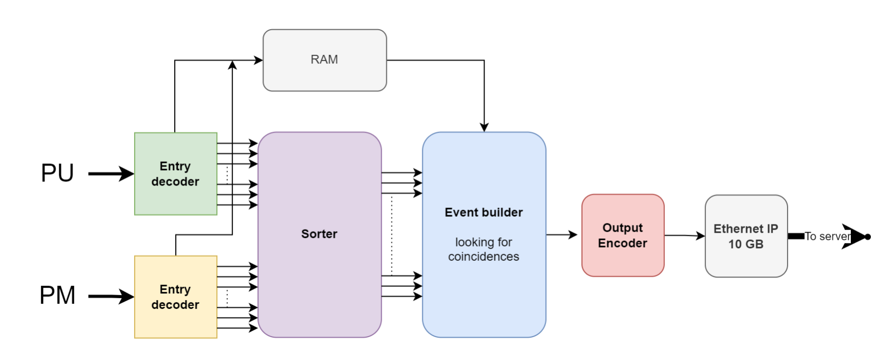
The architecture for implementing the scheme of Fig. 2.1 has been developed. The sorter implements a bitonic sorting algorithm using an architecture based on aggregation of elementary modules. One of the main interest with this approach, is that it can be pipelined, in order to easily reuse basic merger blocs in the final sorter design. However, a balance must be struck between the number of pipeline stages and the complexity these stages induce on the multiplexers that need to be added to the final architecture.
Another interesting point is that this block construction, this modularity, makes it much simpler to
distribute the sorter over several boards. Python script has been developed to automatically generate
this type of sorting architecture, depending on hardware constraints.
The data selection process is based on strict coincidence conditions, specifically targeting positron-electron annihilation events. Only these events are considered relevant; all other data is regarded as noise and is not transferred to the PC. This approach significantly reduces the computational load on both the network and the server. For an event to be considered, two critical conditions must be met:
• Temporal Proximity: The data must be temporally close, with a small ∆T, ensuring that the data
points are from the same positron-electron annihilation event. Since the timestamps are sorted
in order, the comparison is simple neighboring timestamps. This is achieved by subtracting the
timestamps and checking if the result falls within the threshold.
• Different Sources: Once the temporal condition is validated, the next step is to compare the
sources of the data. The data points must come from two different sources: from a PU (i.e. charge
information) and the other from a PM (i.e. light information). To perform this comparison, a dedicated identification bit in each data is checked. If the bits differ, it confirms that the data
originates from different sources.
If both conditions are satisfied, the data is considered to come from the same positron-electron
annihilation event, detected by both the PU and the PM. The next step is to retrieve the corresponding
data from RAM (previously stored by the decoder). Finally, all the relevant data are concatenated
into a 96-bit packet which is then sent to the Ethernet controller for transmission to the
server.
Our architecture will apply the ∆T single window technique to identify coincidences in our data
flow. Once an event has arrived, a ∆T time window will be triggered, and then all incoming event
during this time frame is considered to in coincidence, else it is considered as noise.
2.2.4 Performance assessment
A small scale event builder has been implemented on a Kintex KCU-116 Ultra−Scale+ FPGA board. The results have been generated for a a 4P Us × 4PMs input data. The required bandwidth of XEMIS2 has a mean value of 340 MB/sec, equivalent to 2.7 GB/sec. The maximum bandwidth of the FPGA implementation of the event builder is 800 MB/sec or 6.4 GB/sec, well above of what is required.
2.3 Hiring employees
R&D engineers:
Clément Davril: April 2023 – October 2024
Afshin Seraj: Hune 2023 – October 2024
2.4 Publications
C. Chavet, C. Davril, A. Seraj et G. Demezet, “Next Generation 3-gamma PET with Xenon Liquid Camera using a High-Throughput Hardware Event-Builder Architecture”, submitted to IEEE TRANSACTIONS ON MEDICAL IMAGING
C. Davril, A. Seraj, G. Demezet et C. Chavet, “High-throughput hardware event-builder architecture for 3-gamma imaging PET”, submitted to the 13th European Conference on Clinical Neuroimaging ECCN ; 2025
3 WP3 Acceleration of the reconstruction process for real time 3-γ imaging
3.1 WP presentation
Artificial intelligence has already demonstrated its potential within the field of medical image processing for tasks such as segmentation, denoising, super-resolution or classification. On the other hand, in the last couple of years, there has been an increasing interest in the deployment of AI within the field of raw data correction and the image reconstruction process. Potential advantages include the real-time execution once the model is trained and the potential to directly correct the physics principles of the detection process within the reconstruction task. The disintegration events from emitters used in 3- gamma imaging are processed one by one in order to determine the position of the 3rd gamma emission. Within this context, analytical methods are time-consuming and lead to inaccurate models. Artificial intelligence approaches, coupled with realistic Monte Carlo simulations (MCS) have the potential to solve this problem.
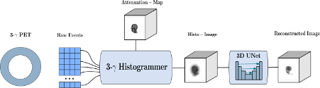
The Direct3γPET pipeline is a comprehensive solution designed to address the challenges of 3-γ PET imaging. The proposed solution is divided into three key parts: Sequence and Compton Cone Building, Histo-Image Building, and Final Image Reconstruction. Each part includes multiple subtasks, each contributing to the overall goal of accurate and efficient image reconstruction.
The full pipeline is shown in the figure below:
Part 1: Sequence and Compton Cone Building
- Event Detection:
- The process begins with detecting raw 3-γ events from the PET scanner. Each event represents a series of photon interactions that occur when gamma photons interact with the detector material.
- Photon Interaction Sequencing:
- Modified Interaction Network (MIN): To correctly sequence the photon interactions, a Modified Interaction Network (MIN) based on a graph neural network (GNN) is employed. This network is designed to handle the complex task of determining the order of interactions, particularly in cases where there are multiple interactions. The correct sequencing of these interactions is essential for the accurate construction of the Compton cone.
- Sequence Determination: The MIN processes the detected interactions, analyzing both the energy and spatial data to establish the correct order. This sequencing step is crucial because it directly impacts the accuracy of the subsequent Compton cone construction, thus the estimation of emission point.
- Emission point estimation:
- Cone Construction: Once the correct sequence of photon interactions is determined, the Compton cone is constructed. The angle of the cone is determined by the Compton scattering angle of the first interaction, and the axis of the cone is defined by the line connecting the first two interaction points.
- Emission Point Estimation: The emission point is estimated by finding the intersection between the Compton cone and the Line of Response (LOR). The LOR is defined by the two detected 511-keV photons that result from the positron annihilation. This intersection helps to narrow down the possible locations of the radioactive source, providing more precise information for image reconstruction.
Part 2: Histo-Image Building
- Line of Response (LOR) Processing:
- Blurring Effects and Detector Response Error Propagator (DREP): The detected events are processed along the LOR to account for blurring effects caused by detector imperfections. The Detector Response Error Propagator (DREP) method is applied to estimate the uncertainty in the Compton angle. This uncertainty arises due to errors in both spatial and energy measurements. These errors are modeled using a non-symmetric Gaussian distribution, which more accurately reflects the nature of the blurring effects compared to traditional symmetric models.
- Uncertainty Management: The DREP method incorporates the uncertainties in both energy and spatial resolution, which are crucial for accurately estimating the Compton angle and, consequently, the emission point. By propagating these uncertainties along the LOR, the method provides a more realistic representation of the detected events, reducing potential errors in the reconstruction process.
- Histo-Image Generation:
- Non-Symmetric Gaussian Modeling: The DREP method generates a non-symmetric Gaussian function that models the distribution of potential emission points along the LOR. This approach allows for a more accurate estimation of the emission points by taking into account the directional uncertainties associated with the detected events.
- Attenuation Correction: Attenuation correction is applied to account for the absorption of both 511 keV and 1,157 keV gamma rays as they pass through the scanned object. This correction is essential for accurately reconstructing the activity distribution, especially in regions of the body where attenuation effects are significant, such as dense tissues or large organs.
- Histo-Image Creation: The corrected data is used to generate a preliminary histo-image. This image represents the spatial distribution of the detected radioactivity within the scanned object. The histo-image serves as the foundational layer for the subsequent image reconstruction process, providing a detailed map of the detected events that will be refined in the final stages.
Part 3: Final Image Reconstruction
The final step of the Direct3γPET pipeline uses a generative model based on an encoder-decoder Convolutional Neural Network (CNN) to refine the preliminary histo-image and produce the final reconstructed image.
- Deblurring and Denoising:
- The generative model processes the initial histo-image to remove blurring and noise, which are common issues in 3-γ PET imaging. The encoder-decoder CNN is designed to keep important details in the image while reducing noise, resulting in a clearer and more accurate output.
- Adversarial Training:
- The CNN is trained using adversarial methods, where the generative model creates images, and a discriminator network tries to tell the difference between these generated images and real ones. This training method pushes the CNN to produce images that closely resemble the actual distribution of radioactive sources, leading to realistic reconstructions.
- Attention U-Net Architecture:
- The model incorporates an Attention U-Net architecture, which uses attention gates to focus on the most important areas of the input image. This helps the network to reduce irrelevant information and improve the accuracy of the final image by maintaining key structural features.
- Final Image Reconstruction:
- The generative model produces a fully reconstructed 3D image that accurately represents the scanned area. The final image is a balance between including detected events and achieving precise reconstruction, making it useful for clinical and research purposes.
3.2 Results
- Photon Interaction Sequence Determination:
- Performance of MIN: The Modified Interaction Network (MIN) was tested against other methods, such as the dϕ-criterion and fully connected neural networks (FCNN), for predicting photon interaction sequences. The results showed that the MIN provided accurate predictions, particularly for events involving more than two interactions. The MIN approach was able to effectively handle the complexities associated with multiple interactions, making it a reliable choice for this task.
- Accuracy in Sequence Determination: The accuracy of the MIN in determining the correct sequence of interactions was higher than that of the other tested methods. This was particularly important for reconstructing the Compton cone, as the correct sequencing directly impacts the accuracy of the emission point estimation.
- Image Reconstruction:
- Comparison of Reconstruction Methods: Different methods were tested for image reconstruction, including those that incorporated the interaction ordering algorithm. The results indicated that the method using this algorithm produced images with better structural preservation and noise reduction compared to other approaches. The use of adversarial training in the CNN further improved the quality of the final images by enhancing structural details and reducing noise.
- Impact of Noise and Blurring: The reconstruction methods were evaluated for their ability to handle noise and blurring in the histo-images. The CNN, particularly when trained adversarially, was effective in mitigating these issues, resulting in clearer and more accurate images. The attention mechanisms in the U-Net architecture also contributed to the refinement of the images, ensuring that the final output was both detailed and reliable.
- Overall Performance:
- Balancing Event Inclusion and Accuracy: The Direct3γ PET pipeline was successful in balancing the inclusion of detected events with the accuracy of the reconstruction process. This balance is crucial for achieving high-quality 3D images that are suitable for clinical and research applications. The pipeline’s ability to accurately reconstruct the emission points, even in the presence of uncertainties and detector imperfections, demonstrated its potential as a powerful tool for 3-γ PET imaging.
The efficiency of the proposed reconstruction method has been assess using phantoms and compared with state-of-the-art PET scan image reconstruction technique. Figure 3.2 shows the results based on phantom and for a 200 kB activity, same dose injected as in PET. As seen in Figure, compared to the ground truth (GT), the Direct3γ method provides an image slightly better than the TOF PET, thus validating the method.

3.3 Hiring employees
Ph.D student: Youness Melak, Ph. D defense: March 2025.
3.4 Associated publications
- Y. Mellak et al, “Three-gamma PET Image Reconstruction“, IEEE NSS-MIC-RTSD, 2022
- Y. Mellak et al, “Gamma Photons Tracking using GNNs“, RITS, 2022
- Y. Mellak, et al. “Direct 3γ PET: A Pipeline for Direct Three-gamma PET Image Reconstruction.” arXiv preprint arXiv:2407.18337 (2024)
4 Conclusion
The RETIREX project was ambitious, not all its research goals have been achieved. Nevertheless, significant improvments have been made in key areas of the XEMIS project. Accuraelty counting the number of photons on each PM pave the way the fiduciarisation of the camera volume, that will allow reducing the number of data to take into account to reconstruct the event. The event builder proposed can process the data to generate the event at the required speed, while removing noisy data. The events built are then sen via a 10GS/s ethernet block to the computer performing the image reconstruction. The artifical intelligence apparoach taken for image reconstruction shows that it performs well under the same radioactivity as the state-of-the-art PET scan. Futur work should put all the results together to prove the proposed improvements can lead to a real time scanner.