
Description of the innovative action : «mmWSounder»
Design of a 60GHz channel sounder for 5G and WIFI communication
The objectives of the “mmWSounder” project is in the continuity of the M5HESTIA project . The consortium is the same as M5HESTIA.
1. Feedback of the main results of M5HESTIA
The main results obtained by the M5HESTIA project are for each major topics:
- Antenna et RF architecture : a flexible antenna system, with or without transmit array antenna :
- With the transmit array antenna a long-range (outdoor) channel sounder with analog and digital beamforming.
- Without the transmit array antenna a short-range (indoor) channel sounder with 100% digital beamforming.
- Antenna customizable with the b<>com system
- Propagation and channel modelisation
- Study on tracking techniques (mobile channels) and on the modeling of the mmW MIMO channel
- Deterministic millimeter channel simulator PyLayers https://github.com/pylayers, validated by measurements at Aalto University (Finland)
- Algorithm : optimization of hybrid systems (repartition between analog and digital processing)
- System performance analysis on geometric channels: beamforming by directional vectors, resource allocation and user grouping, application to spatial modulations,
- Theoretical studies of capacity on geometric channels: channel stiffening, large parsimony representation
- Démonstrator b<>com
- With the elements provided by the project (antennas and front-ends): design of a beamsteering based demonstrator (analog separation of 2 independent streams in 2GHz bands, with 256 QAM and LDPC coding).
2. Why an innovative action ?
At the end of the M5HESTIA project, in addition to the numerous theoretical studies conducted and the demonstrator developed, 60GHz antennas and front-ends will be available. They will allow to initiate measurement campaigns which will be carried out in cooperation with Orange Labs (Belfort).
The results of the M5HESTIA project could therefore be largely consolidated by:
- The design of a mmw channel sounder
- The exploitation of the measurements made by this sounder by different partners
3. Work dezcription in “mmWSounder” project
The main objective of the requested innovation action is to design a fully automated multi-beam channel sounder capable of performing 360° beam scanning in the horizontal plane and 90° in the vertical plane. This sounder will integrate the 60GHz multibeam RF bottom-end. Depending on its configuration (with or without lens), it can be used for outdoor or indoor measurements. This instrument will then be used for measurement campaigns in different environments that will improve knowledge of the propagation channel for the design of multiuser and massive MU-MIMO devices that can meet the new 802.11.ay standard currently being standardized.
3.1 Tasks
This work will be divided into 2 tasks . The academic partners are involved in the 2 tasks. Orange is mainly involved in the definition of the sounder and the measurement campaigns. The b<>com IRT is mainly involved in the exploitation of the results.
Task 1 : mmw channel sounder at 60GHz (IMT Atlantique)
Hardware Setup
The system is composed by a commercial product of millimeter-wave, which integrate a receiver and transmitter module. The Analog Device EK1HMC6350 is a demonstration board, which include HMC6300 and HMC6301, respectively the transmitter module and the receiver module.
The transmitter is composed of the HMC6300 can operate from 57 to 64 GHz, with up to 1.8 GHz bandwidth. The board supports different modulation provided by a differential baseband I/Q input. A heterodyne IF architecture in addition of an RF mixer is used inside. The Figure shows the architecture.
The R&S SMJ 100A is currently used to generate the 71.42857 MHz reference clock to control channel bandwidth (250 MHz). Moreover, the equipment is also used to provide I/Q signal with a bandwidth of 80 MHz in single-ended in order to emit a flat spectrum signal. To increase the RF output power, we consider an amplifier with a gain of 25 dB and a P1dBm of 25 dBm. The antenna could be classic horn antenna with 15 dBi gain.
The receiver part is composed of, currently, a horn antenna with the same specifications as the transmitter antenna. The HMC6301 has a variable gain from 0 to 69 dB. The HMC6301 down-converts the 60 GHz signal to analog I/Q differential baseband signal.
A USRP X310 is used to convert the analog signal to digital. The maximum bandwidth is 160 MHz, and all the equipment are synchronized with a 10 MHz signal reference from rubidium.
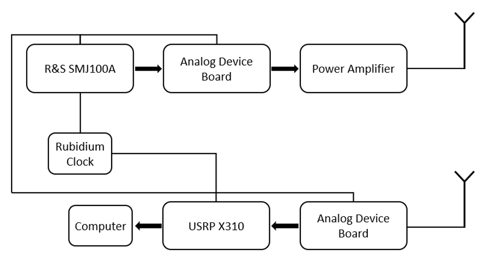 Figure : Mmw channel sounder architecture
Software Setup
An addition of the hardware setup, a software has been developed on PyQt from python to control the USRP, the receiver and transmitter card. The software proposed by Analog Device is only present on windows system and cannot control specific element. The Figure 8 shows the control window used to control the different gain on the card.
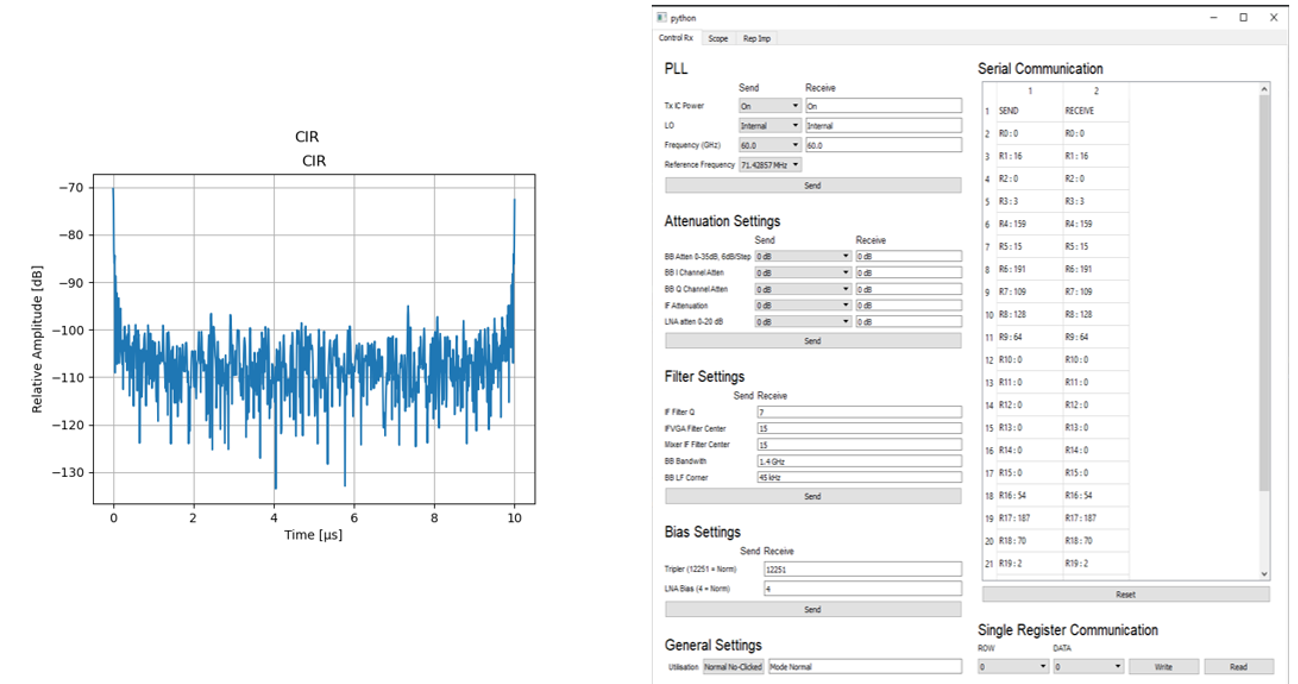 Figure: Window Control Receiver (right) part and example of CIR measurement
Specification
This system employs the Wiener inversion to calculate the CIR of the channel. A back-to-back calibration file is recorded with a direct connection between. For 160 MHz, the time resolution is equal to 6.25 ns. The maximal duration of the sounding process at a given position corresponds to 1000 points of measurements, so a maximal duration of 10 µs.
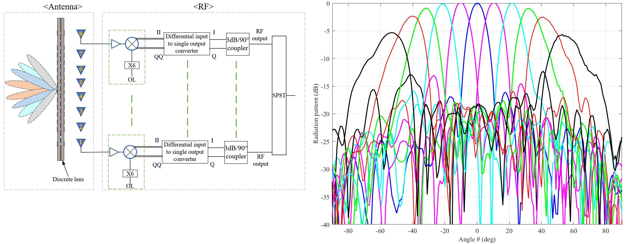
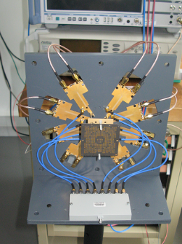
Multibeam 60GHz front-end
Due to the high free space losses at 60 GHz, directive antenna has to be used to obtain a good sensitivity and allowing DOA measurement. In dynamic scenario, a single beam with a mechanical scan is not adapted. A solution based on a fast-electronical switch of different beams is proposed to scan the environment. This approach is acceptable if the switching time is small in comparison to the environment modification, for example a maximum vehicle speed. Due to technological constraint, a linear antenna array is investigated.
Depending on the type of environment and the distance (short or medium), two architectures are proposed. For short distance, a full digital beamforming allows to have a complete freedom about the DOA. But due to the low gain of the antenna, the sensitivity will limit the measurement range. Figure 10 presents the architecture of the mmW front-end with 8 antennas. The main challenge is to minimize the interconnection losses at 60 GHz between the antenna and the 60 GHz downconverter with a high constraint of integration imposed by the half wavelength distance between antennas. Furthermore, the LO (Local Oscillator) of each mixer must be synchronised.
For medium distance, high gain antenna is necessary to improve the sensitivity. We propose to add a transmit array antenna just in front of the array antenna to design a hybrid analogic and digital beamforming. This allows to generate 8 beams every 10° and each with a beamwidth of 10°.
Task 2 : Measurement campain and data exploitation
a) Campagnes de mesures (Orange, IMTA, IETR)
Plusieurs campagnes de mesures seront menées selon les scénarios identifiés pour des applications indoor ou outdoor. Les mesures seront exploitées pour l’amélioration du modèle de canal et la validation des résultats théoriques sur ces canaux réalistes.
b) Analyse et amélioration du modèle de canal (IETR)
Après une analyse des mesures correspondant aux différents scénarios définis dans M5HESTIA (indoor et outdoor), il s’agira de faire évoluer le simulateur déterministe de canaux millimétriques PyLayers.
c) Validation des propositions d’architectures et de traitement numérique associés pour des systèmes MU-MIMO (IETR, b<>com)
Intégration dans les outils de simulations de canaux enregistrés ou du modèle de canal amélioré pour valider les résultats théoriques obtenus dans M5HESTIA sur canaux géométriques ou théoriques.