
Different scientific communities are involved in this project (antenna community, signal processing community, propagation community, digital communications community). They often use the same words with slightly different definitions. This part aims at clarifying the definition we mainly use in this document and for our technical discussions.
1. Basic vocabulary
On Figure 1 a), one elementary “antenna or radiating element” is presented.
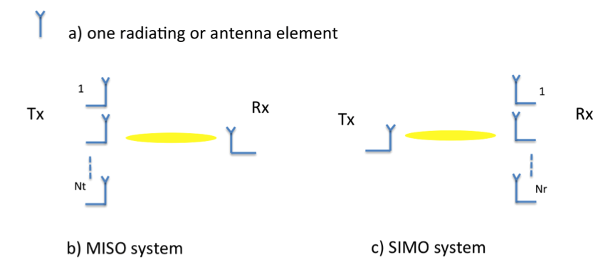
Figure 1: a) radiating or antenna element b) MISO system c) SIMO system
A MISO system with Nt transmit radiating elements and one receive radiating element and a SIMO system with 1 transmit radiating element and Nr receive radiating elements are presented on Figure 1 b) and c) respectively.
For sounding channel, a SIMO system will be developed with a mechanical scanning in the azimuth plane and a digital scanning in the elevation plane.
For transmission studies and demonstration, SDMA will be implemented with a Massive MISO system at the infrastructure side (large Nt) and one radiating element at the user side
2. Analogue beamforming and phase array
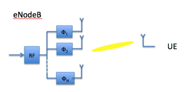
Figure 2 schematizes an analogue beamforming at Tx side with N radiating elements at the transmission side.
The main characteristics at the transmitter side for analogue beamforming are the following:
- N radiating elements

Figure 2: analogue beamforming at Tx side with N radiating elements
- One RF (including frequency transposition, IF)
- One IQ link
- SDMA not possible: only one user per channel at the same time
An analogue beamformer made up with N radiating elements is defined as a phase array, and further denoted “phase array (N)”, see Figure 3.
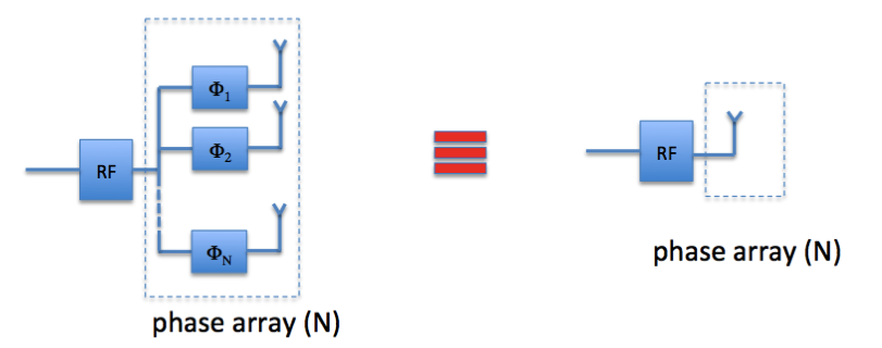
Figure 3: phase array (analogue beamforming with N radiating elements)
3. Digital beamforming
Figure represents an eNodeB equipped with Q IQ links.
Characteristics for digital beamforming:

Figure 4: digital beamforming sor SDMA
- Q radiating elements
- Q “ IQ links”
- Possible SDMA serving Nu<Q
4. Hybrid analogue and beamforming
Figure represents a hybrid scheme with for example Q IQ links and Q phase arrays made up with N radiating elements.
Characteristics of an hybrid beamforming:
-
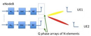
Figure 5: hybrid analogue / digital beamforming
Nt=Q*N radiating elements
- Q “ IQ links”,
- Possible SDMA serving Nu<Q users,

The configuration (links between RF stages and analogue beamformers, number of radiating elements per phase array, etc.) can be adaptive and reconfigurable depending on the criterion defined to serve the different users. This optimisation is part of studies to be carried out during the project