
The role of the Transmitarray Antenna (TA) is to focus the radiation energy in one direction by transforming a spherical wave into a plane wave. It’s composed of unit-cells allowing controlling the phase shift of the electromagnetic wave (Figure 1).
The phase shift distribution is optimized by using discrete phase shift value. To obtain good performance, 8 values (each 45°) has been chosen.
The Figure 2 shows the phase shift distribution obtained in the case of an unifocal transmitarray.
- TA with 20×20 unit-cells (50×50 mm2)
- Ratio F/D = 0.4 (edge tapering -11 dB)
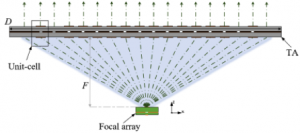 Figure 1: Schematic diagram |
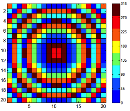 Figure 2 : Phase shift distribution |
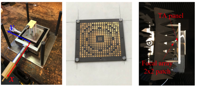 Figure 3: radiation pattern test bench |
The transmitarray antenna has been tested and validated from radiation pattern measurement. The primary source is the 2X2 patch array presented in M5HESTIA 60GHz-FI downconverter part.

Figure 4: Radiation antenna measurements
- Side lobe level (SLL) is < -16/-18 dB (E-/H-plane)
- Cross polarization is < -30/-28 dB (E-/H-plane)
- Full half power bandwidth is 8° in E-&H-plane
The beam scanning is obtained by moving the primary source.

Figure 5: schematic diagram of the beam scanning
 Figure 6: Radiation pattern of the unifocal TA in H-plane at 60 GHz |
The Radiation pattern of the unifocal TA in H-plane at 60 GHz is presented on Figure 6. Unifocal means that the phase error in the aperture is minimum for one primary source position (usually at the centre corresponding to a 0° beam direction).
To improve the beam scanning performance, the principle is to design a multi-focal transmitarray antenna. Usually two symmetric primary source position are defined where the phase error will be minimized (figure). In our case, the focal position corresponds to a 33° beam direction.

Figure 7: Schematic diagram of a bifocal TA

Figure 7: radiation pattern of the bifocal TA antenna in H-plane at 60 GHz
The scan loss is 2.9 dB at ±40° and the gain is around 20dBi.

Figure 8: Gain antenna and comparison of the scan losses for unifocal and bifocal TA
In the case of a scan in both plane (azimuthal and elevation), it’s possible to design a quadrifocal TA (figure 9).
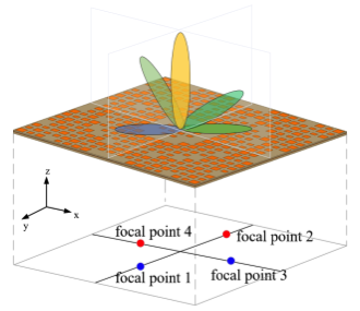
Figure 9: a quadrifocal TA

Figure 10: Comparison simulation- measurement of the radiation pattern of the quadrifocal TA

Figure 11: Measurement of the radiation pattern of the quadrifocal TA

The angular range with scan losses below 2dB are respectively of 40° for the unifocal TA and 60° for the quadrifocal TA.