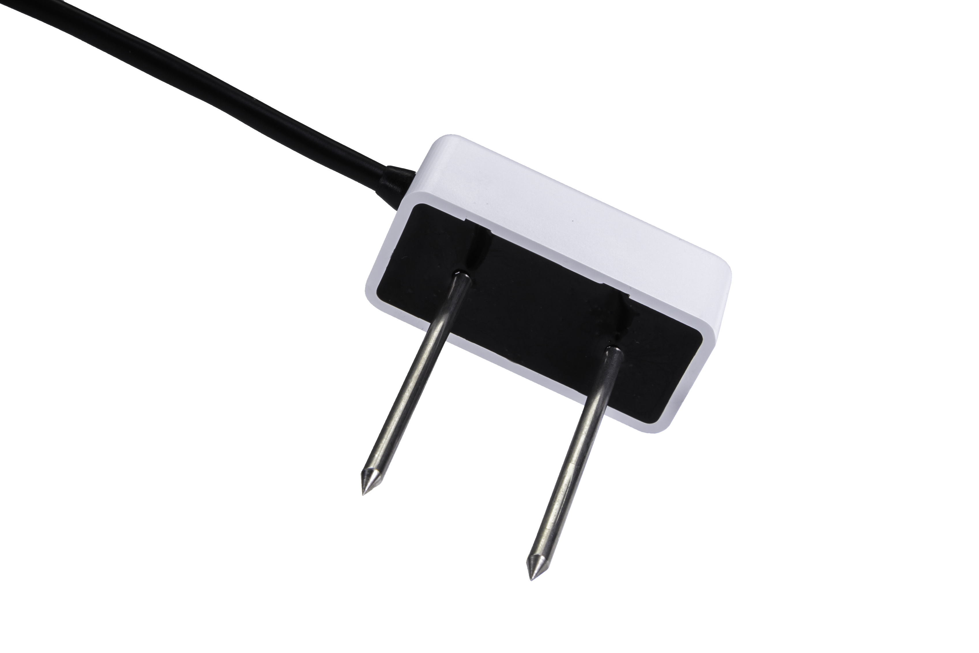
To measure the soil moisture we are using the GS1 and EC5 from the Decagon company. Those two sensors measure Volumetric Water Content and return an analog value between 1V and 2.5V.
GS1 Manual http://publications.decagon.com/Manuals/14640_GS1_Web.pdf
Due the power consumption of the moisture sensor, we developed a digital switch to power up and down the GS1 or EC5 sensor.
The circuit is shown here.
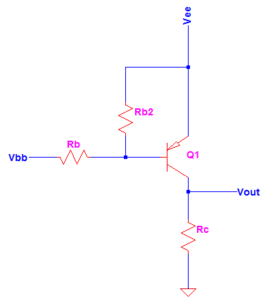
Where the transistor used is a BC807 (a general purpose switching transistor, with a very slow Vce saturation voltage , around 0.02V). http://pdf1.alldatasheet.com/datasheet-pdf/view/16107/PHILIPS/BC807.html
Vee the power supply (2 AA Batteries)
Rc is the sensor itself
Rb 1K ohm
Rb2 10K ohm ( only to ensure that the base of the transistor will not float if ever the Vbb is derived from a circuit that cannot provide logic high)
Vbb Digital output of the mote. (Active low.)
Note: The output voltage of the GS1 Sensor is higher than the maximum allowed to the A/D mote convertor, so we installed a resistor voltage divider installed in the analog output of the sensor. In the example were used 2 10Kohms resistors
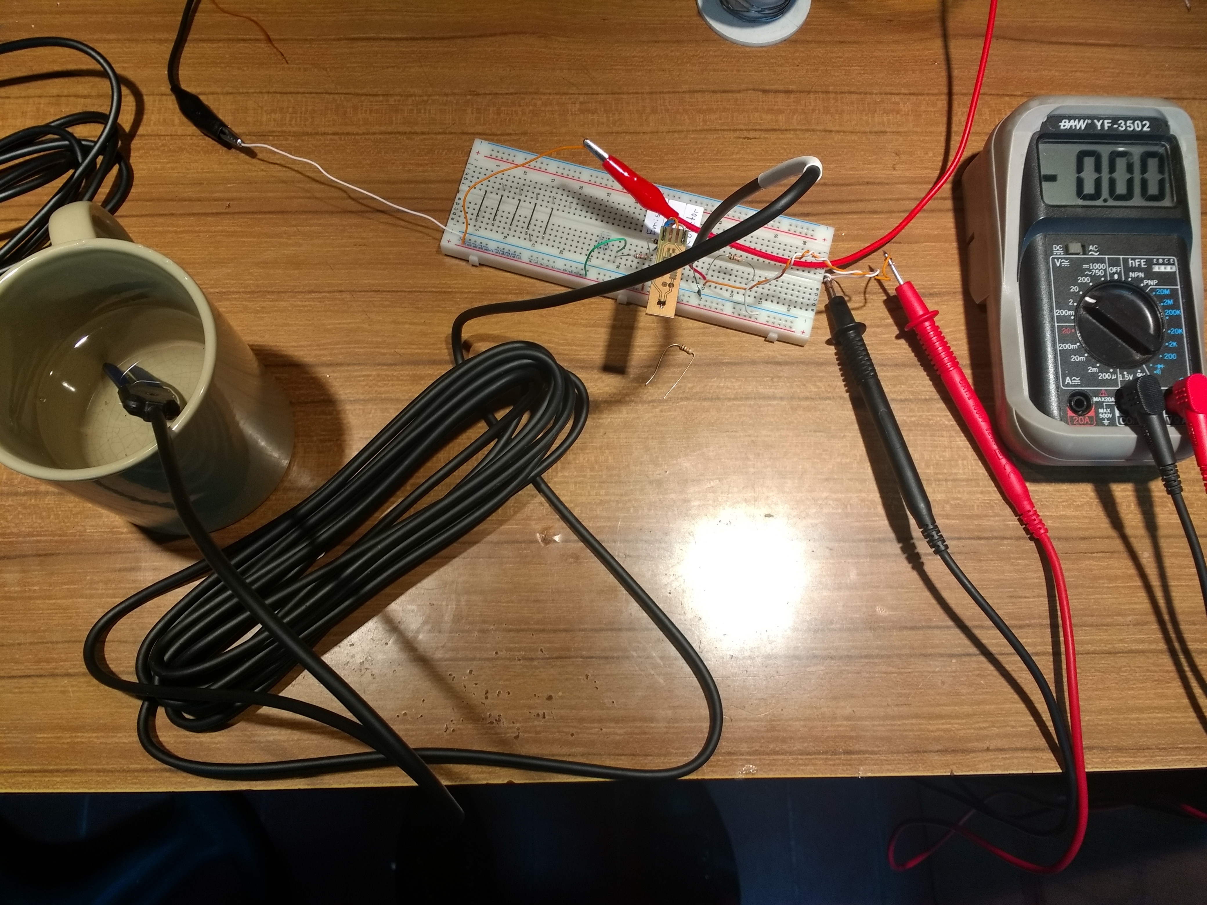
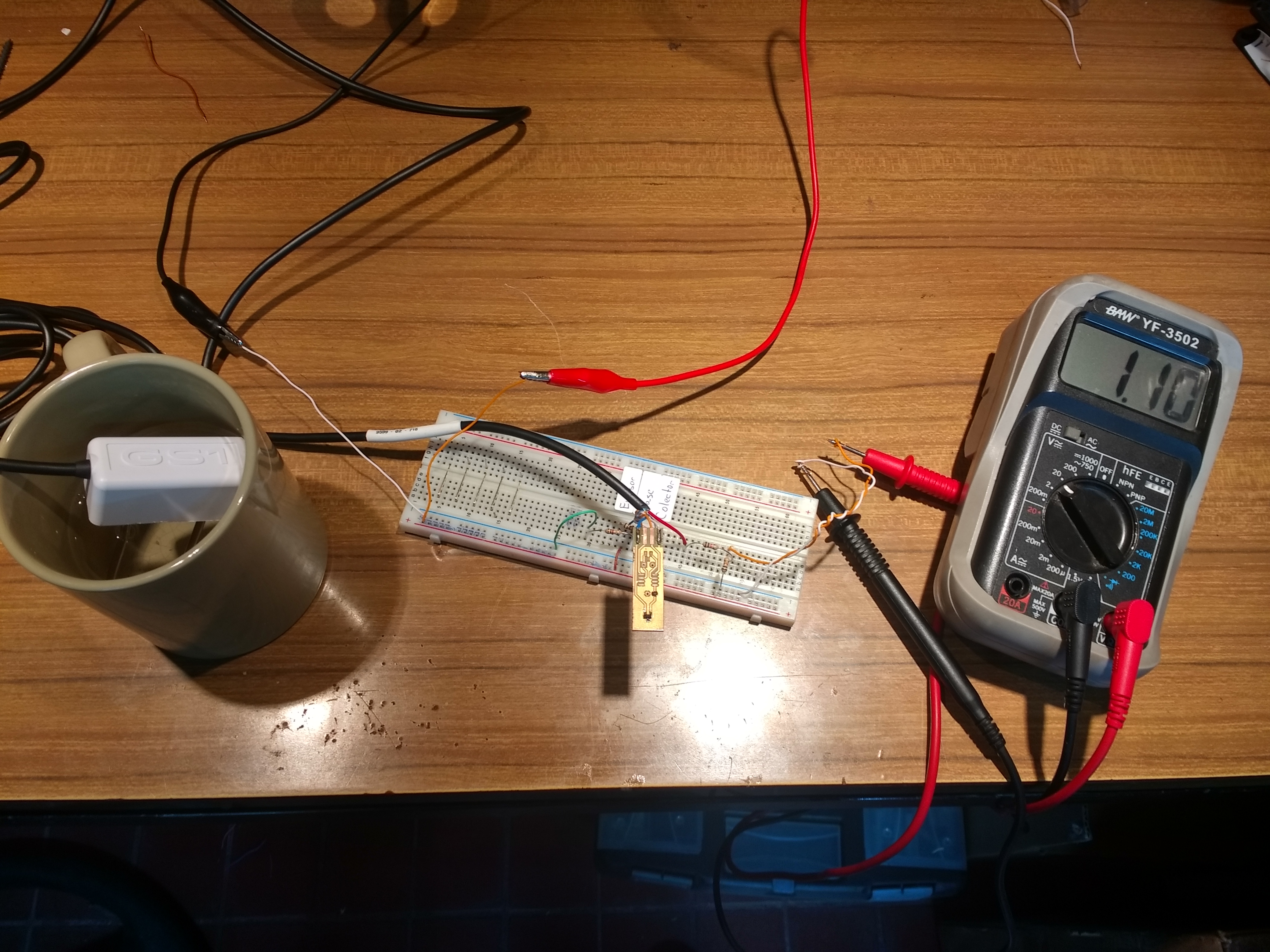
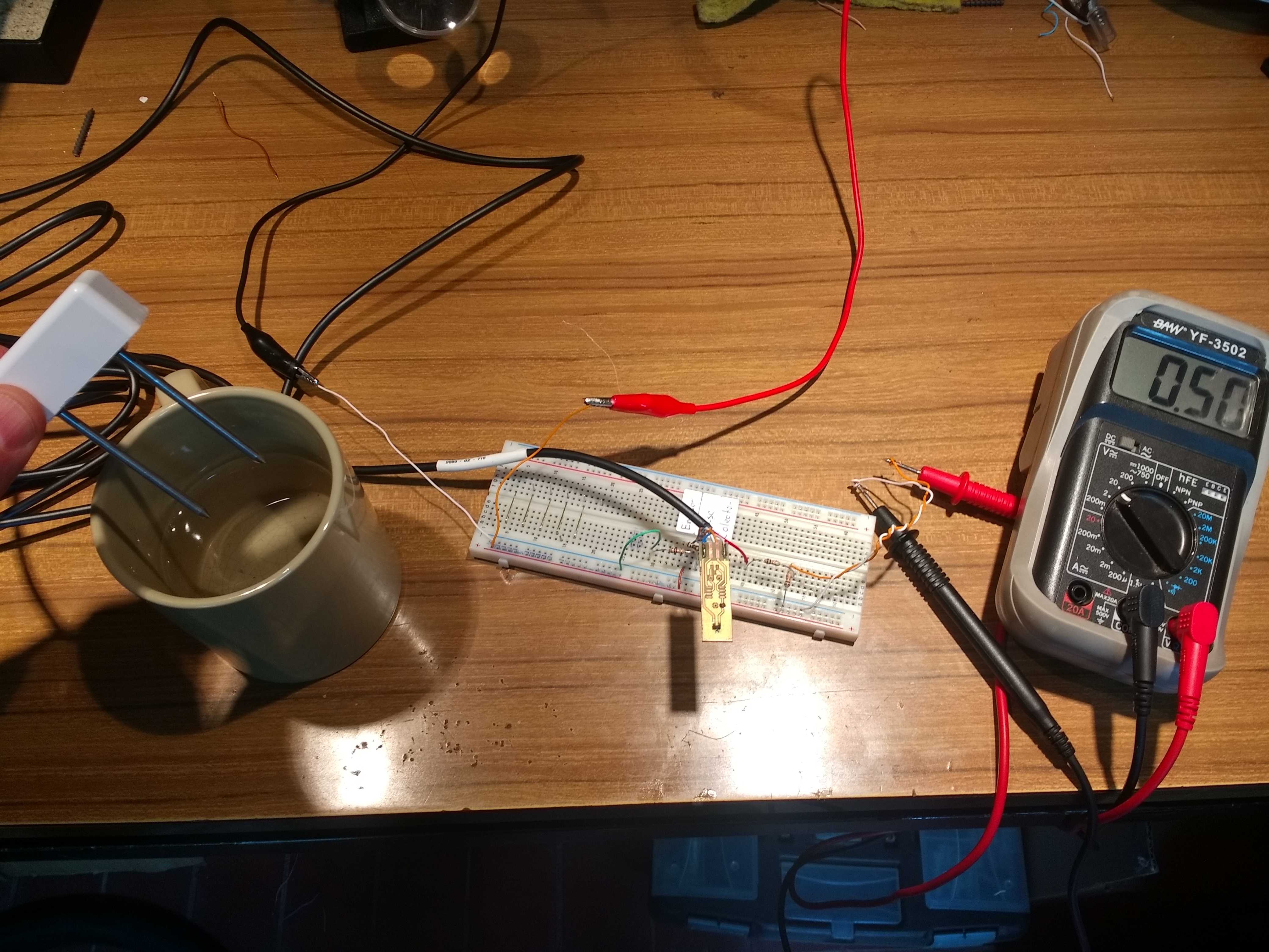
Some test done @ Gridtics. The first with 100% humidity (1,1V), and the second with 0% humidity (0,5v). The power voltage was 3.0V
To disable the sensor, the Vbb was pulled up to Vee
EC5 Manual http://manuals.decagon.com/Manuals/13876_EC-5_Web.pdf
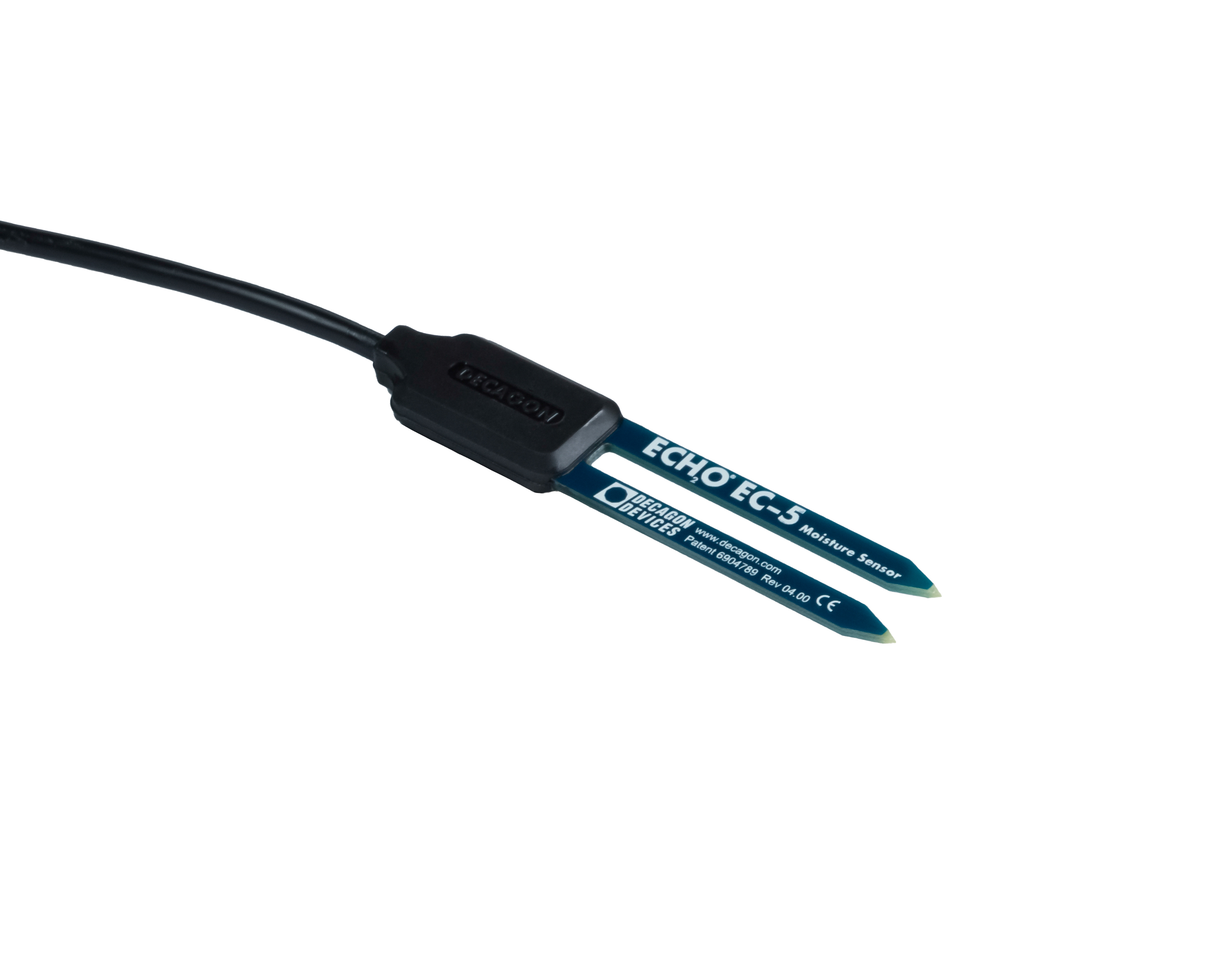
The circuit used to test the sensor was the same than the previous circuit. The main difference is the output voltage.
From the manual “Output voltage: 10 to 40% of the excitation voltage (250mv to 1v at 2.5V excitation)” So, it was unnecessary to use a resistor voltage divisor.
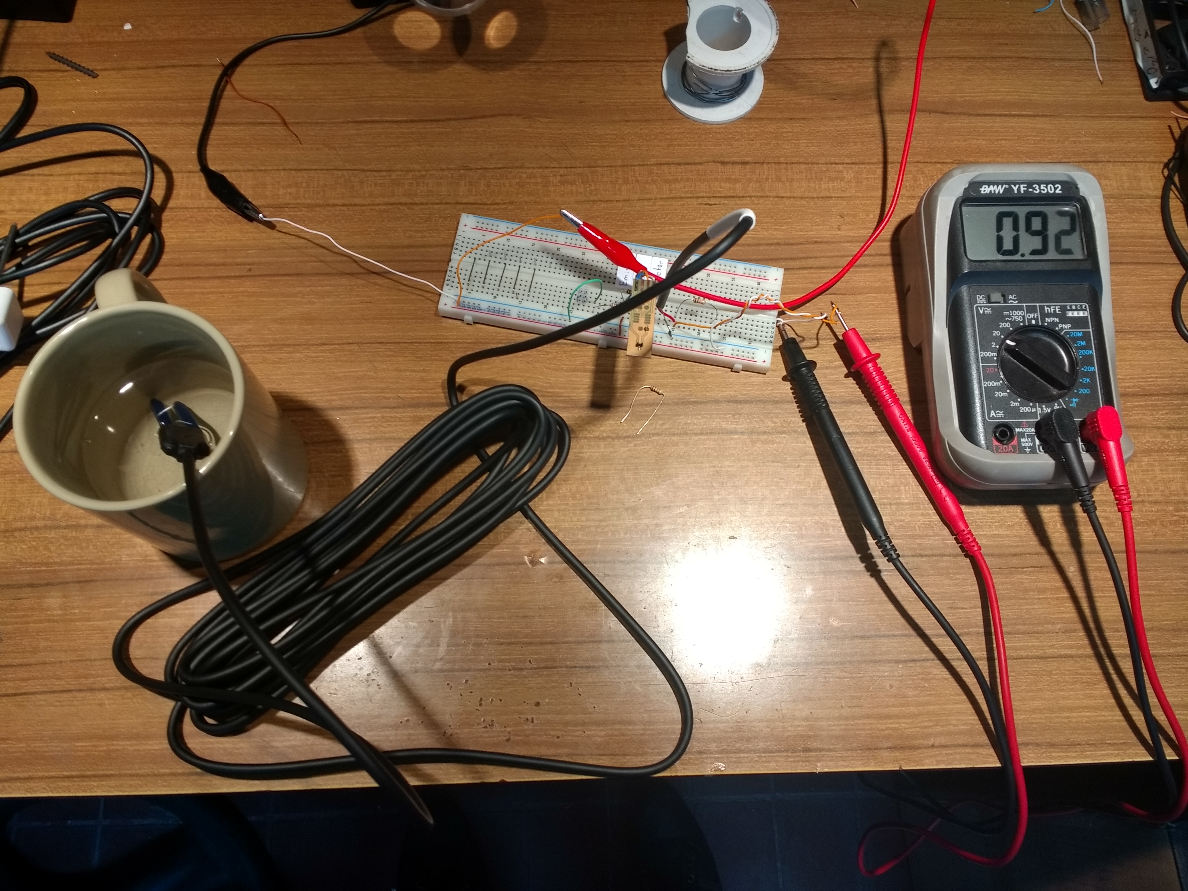
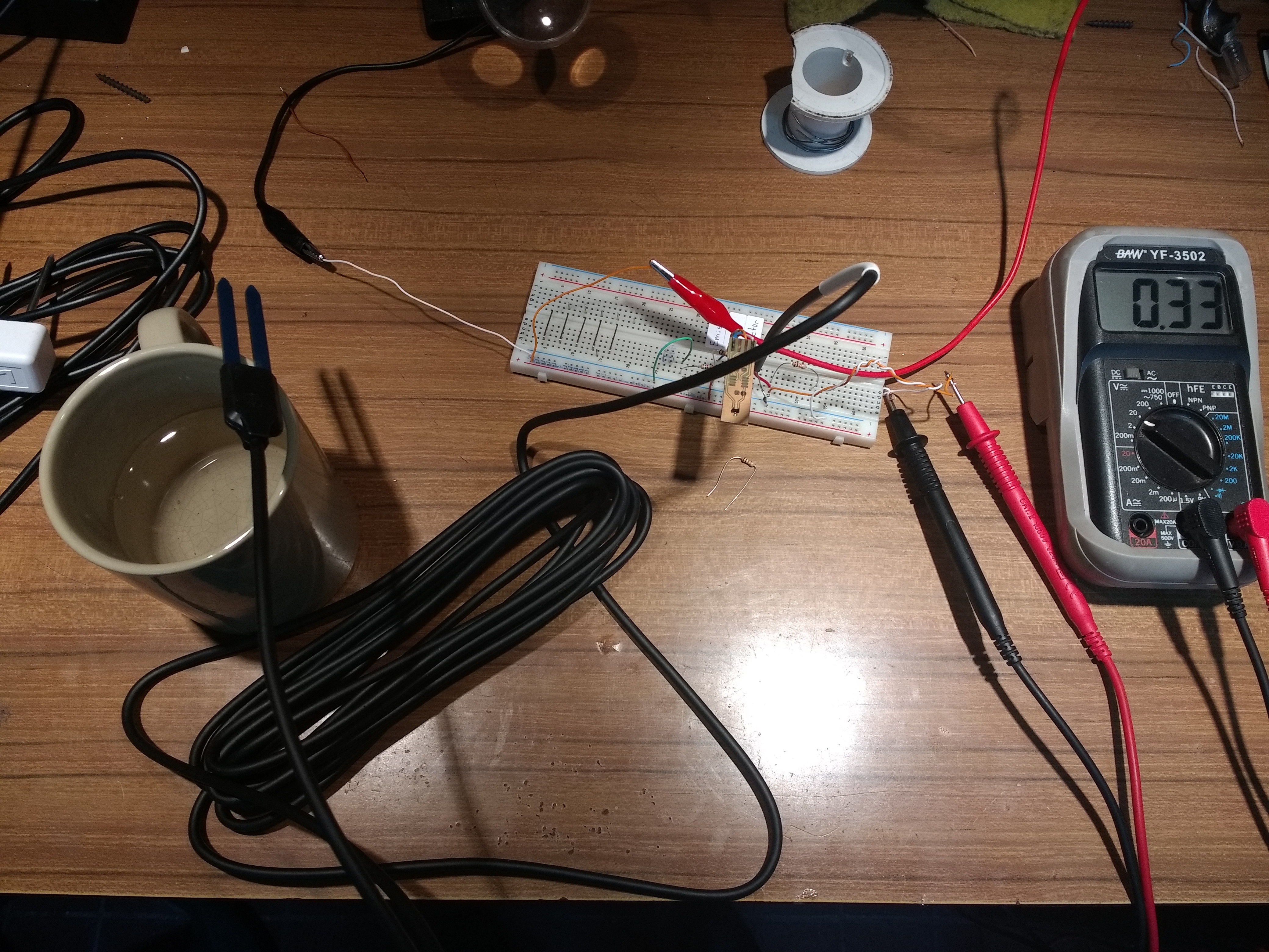
Some test done @ Gridtics. The first with 100% humidity (0,92V), and the second with 0% humidity (0,33v). The power voltage was 3.0V
And once again, to disable the sensor, the Vbb was pulled up to Vee.