From design to mesh generation
using FreeCAD and GMSH
In order to simulate a mechanical object using Finite Element Modeling (FEM), a discrete version of its volume is required. This volume, referred as volumetric mesh will serve as a domain for FEM computation. The aim of this tutorial is to explain how to design a closed surface description made of triangles, and create a volumetric mesh from it. Several tools exist for 3D modelisation such as OpenSCAD (http://www.openscad.org/), FreeCAD (https://www.freecadweb.org/), or Blender (https://www.blender.org/). Several tools also exist for volume meshing such as GID (http://www.gidhome.com/), CGAL (http://www.cgal.org/), or Gmsh (http://geuz.org/gmsh/). For CGAL, a dedicated plugin is available within the SOFA framework (see a documentation here).
In the following, we will show an example using FreeCAD for the design and GMSH for the mesh generation. We will also try to give useful links.
A. Design and Modeling using FreeCAD
In this section we will give a quick overview of how to design a soft pneumatic actuator using FreeCAD, together with links to more detailed explanations.
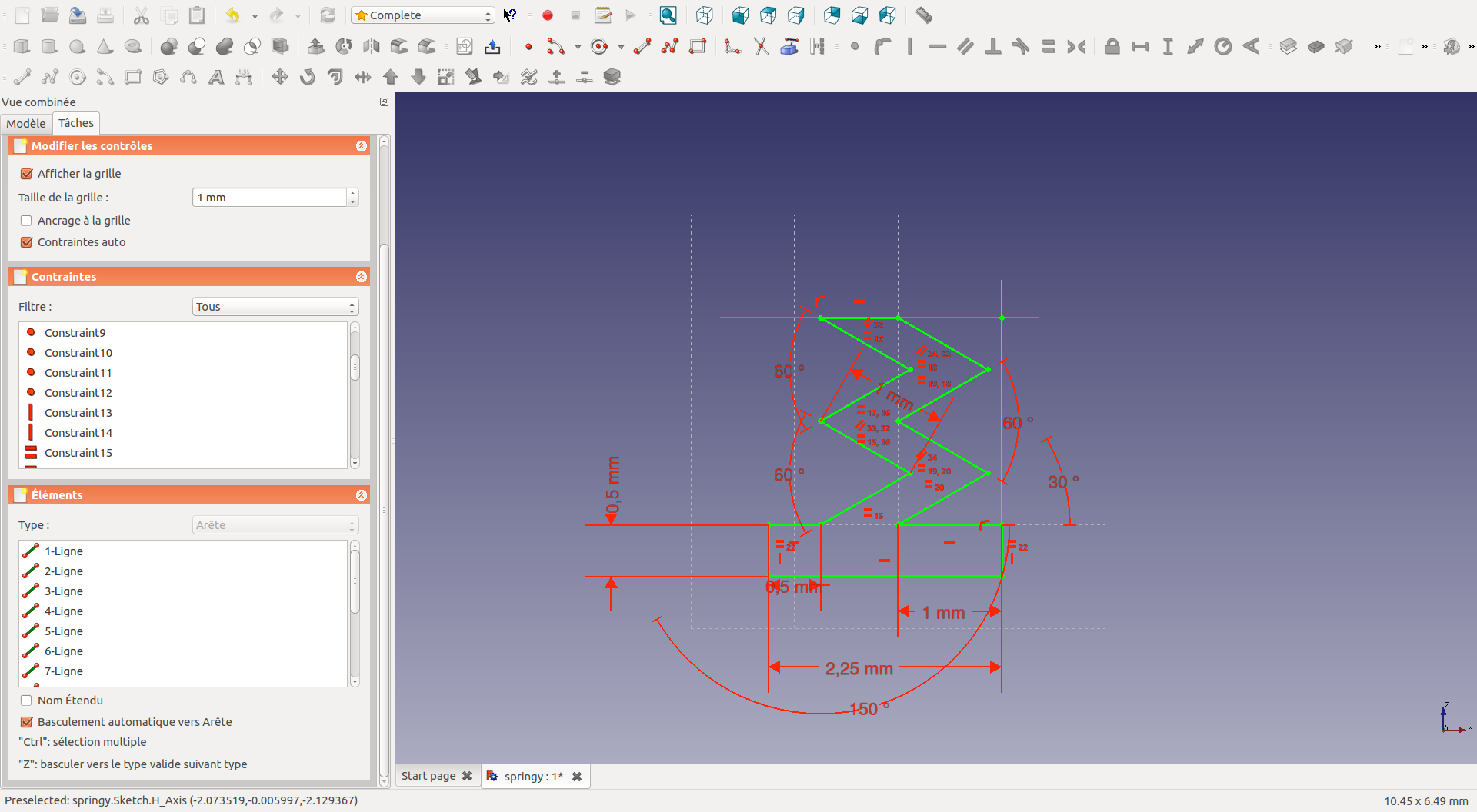
1. Sketch
The first step is to sketch your structure. In FreeCAD you have several workbench (Part, Sketcher…) showing the different corresponding tools. Here we choosed the “complete” workshop, which displays a sample of all the workshops. Clic on sketch (![]() ). When sketching, keep in mind that there are tools to automatically generate symetries. Here are the tools to draw your sketch (
). When sketching, keep in mind that there are tools to automatically generate symetries. Here are the tools to draw your sketch (![]() ) and to set constraints (
) and to set constraints (![]() ). See for exemple this video for a detail tuto.
). See for exemple this video for a detail tuto.
When working with cavity, you can either include the cavity in your sketching or create the cavity later and use the boolean operation tool (difference) to remove the matter.
2. Revolve
The next step is to use the “revolve” tool (![]() ) to create the solid. See for example this video.
) to create the solid. See for example this video.
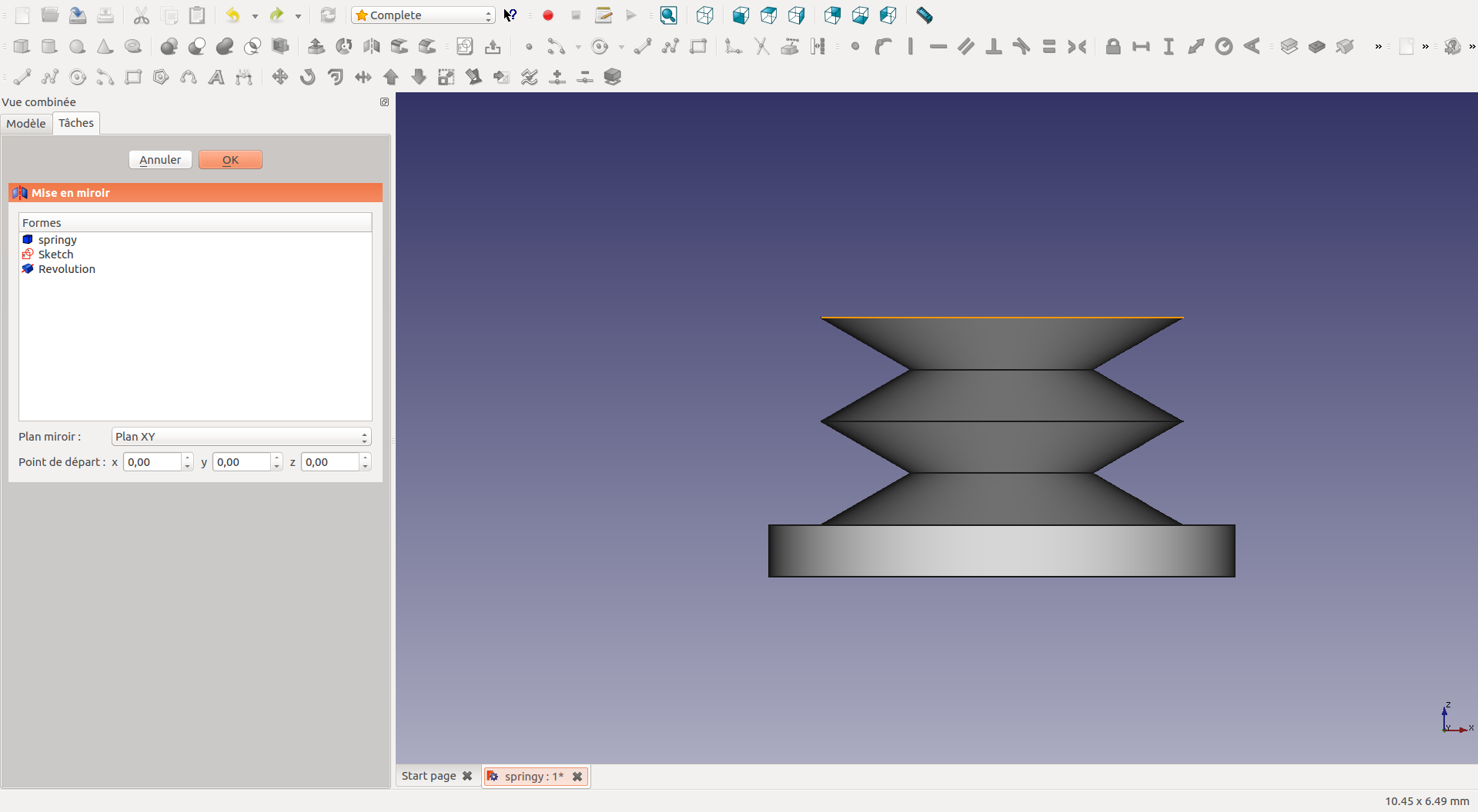
3. Mirror and Fusion
Now we use the “mirror” tool (![]() ) to get our final shape.
) to get our final shape.
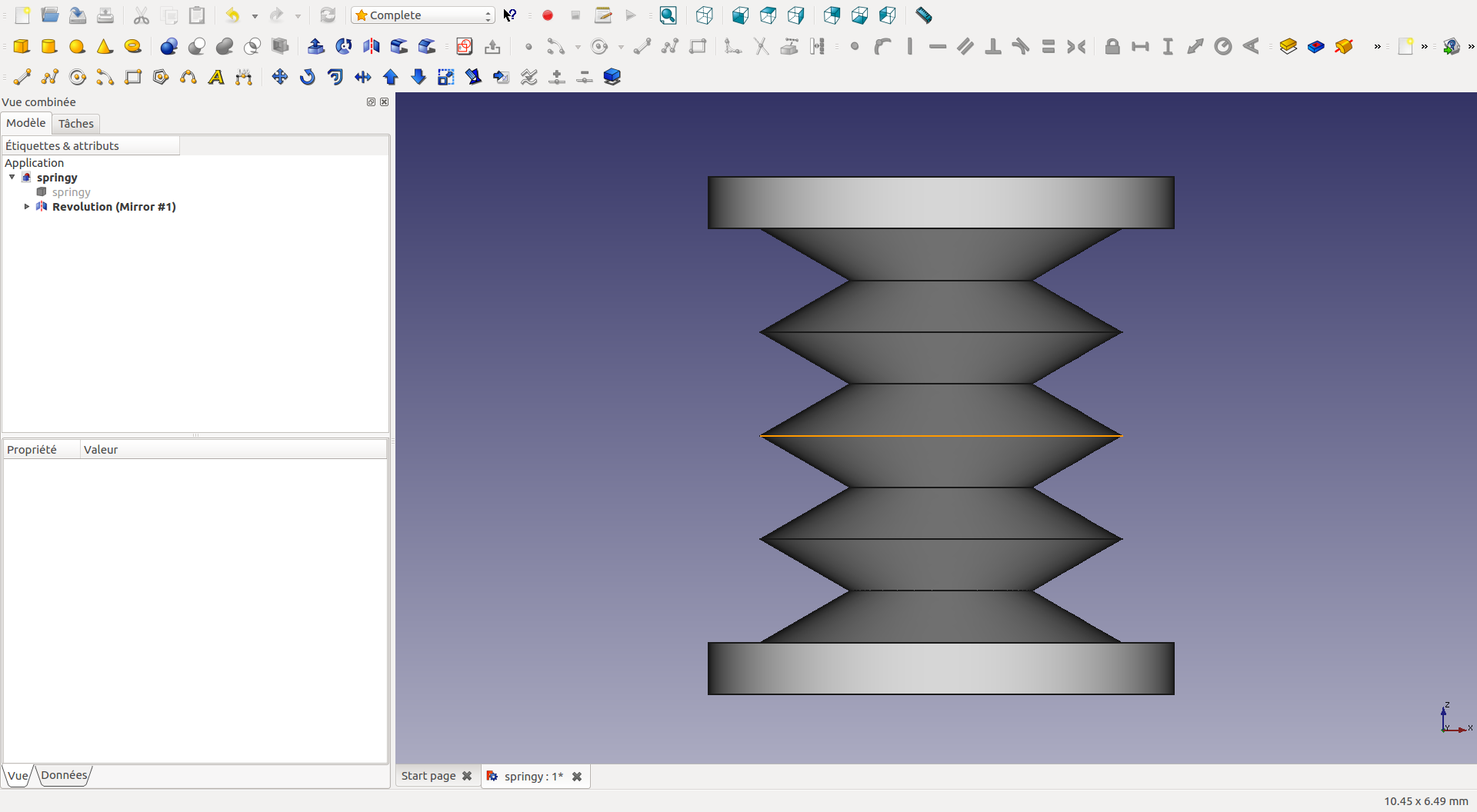
The structure is in two parts:
- the first one generated by the “revolve” tool
- and the second one generated by the “mirror” tool
Select both objects and combine them into a single object using the “fusion” tool (![]() ).
).

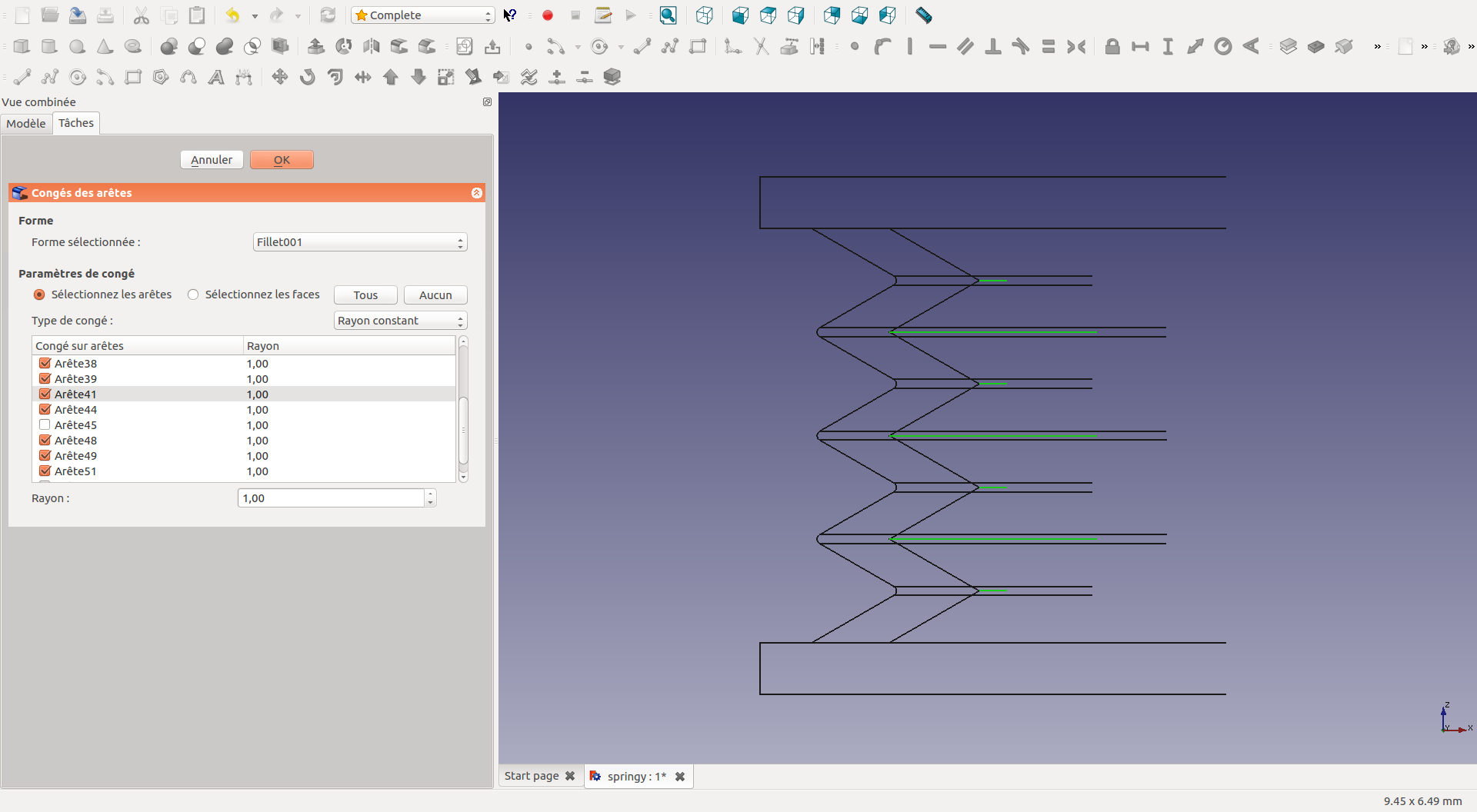
4. Fillet
You can change the view of the object (right clic on the model, appearance…). Now we can both the surface and the inner cavity. Here we will add what we call a “fillet” (![]() ). We mainly remove the sharp angles to ease the 3D print of the mold, and the casting stage of the silicone.
). We mainly remove the sharp angles to ease the 3D print of the mold, and the casting stage of the silicone.

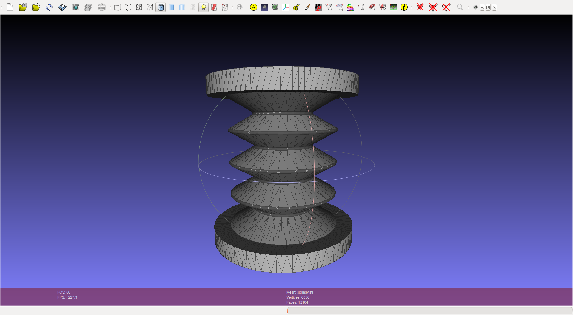
B. Volumetric mesh generation using GMSH
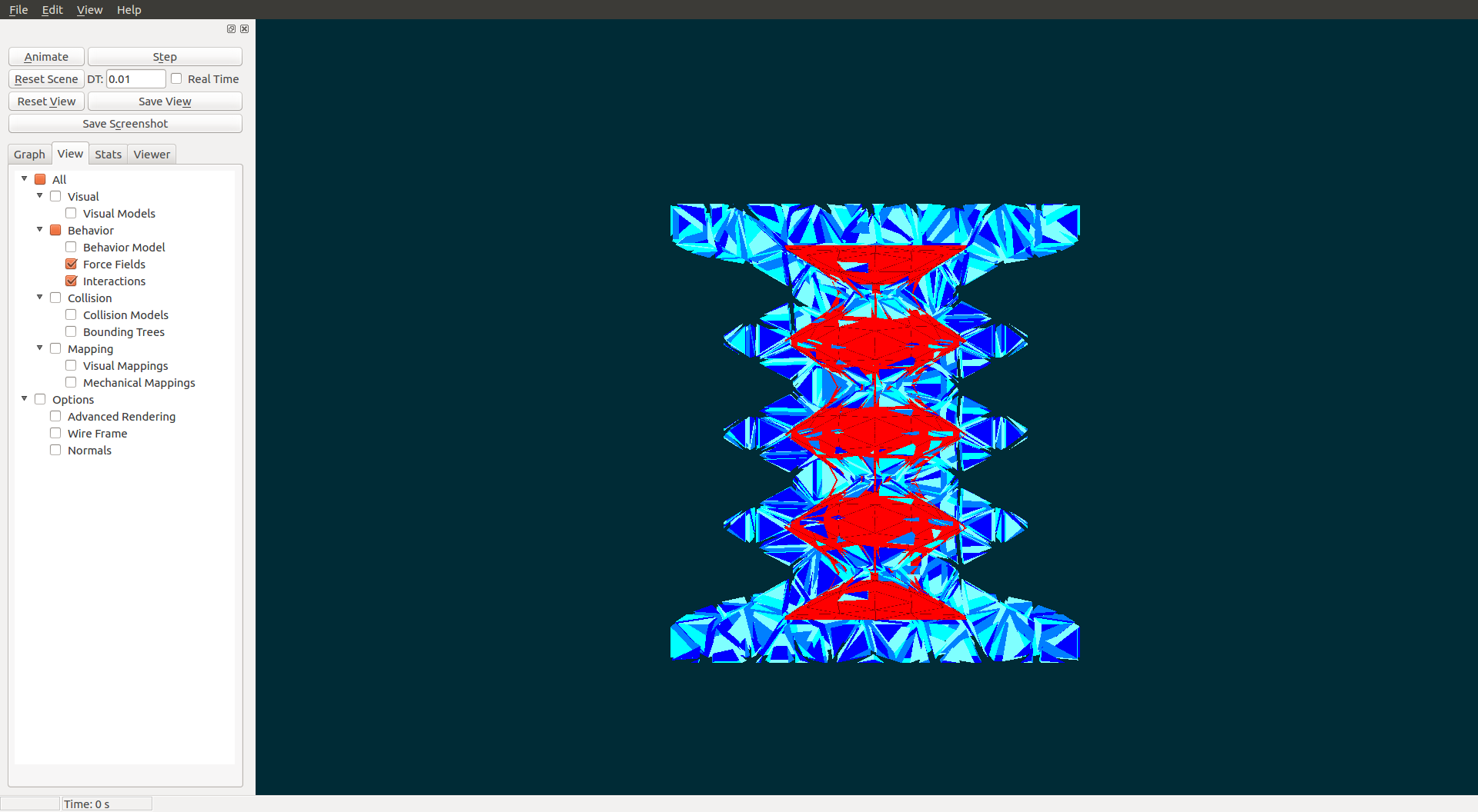
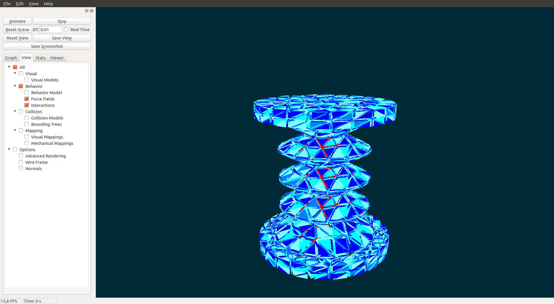
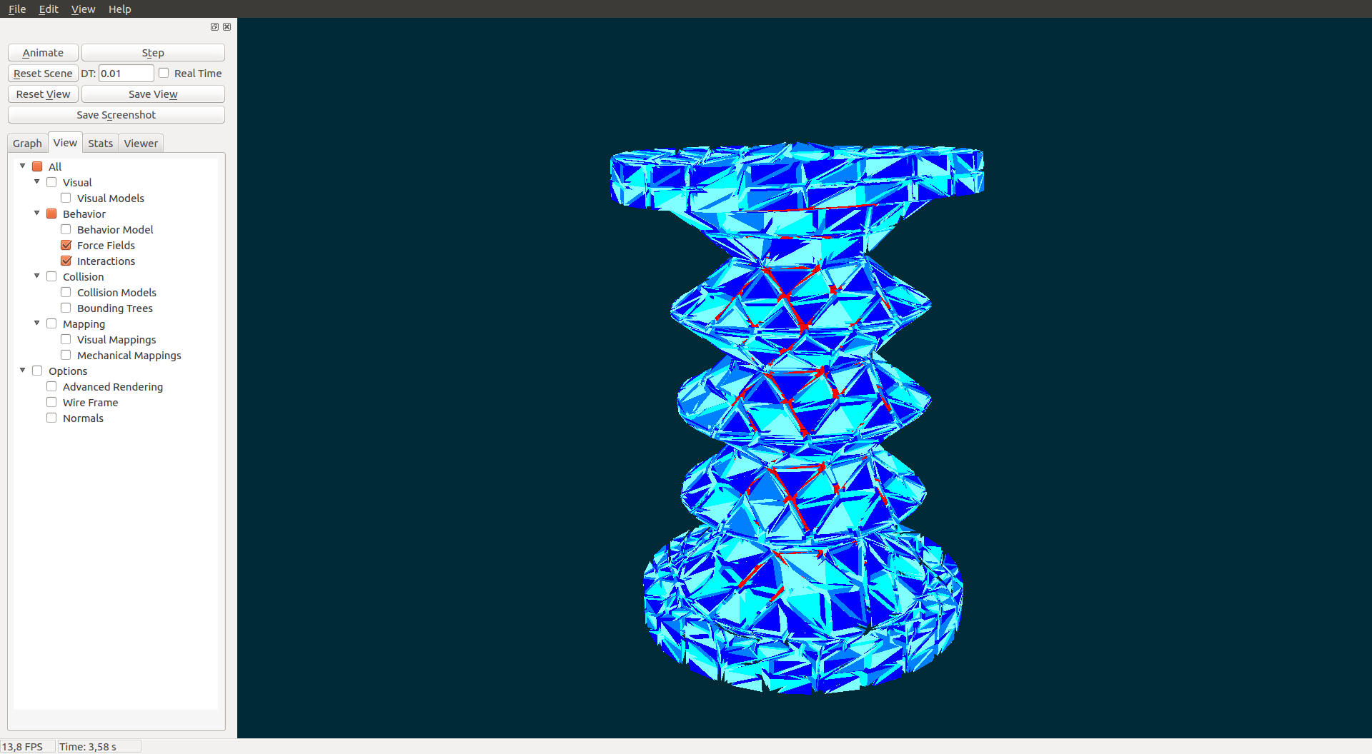
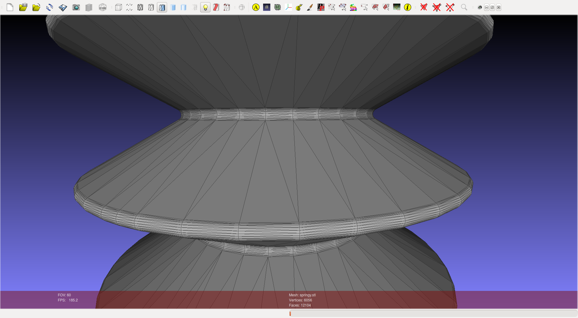
Now we have our 3D structure. Using FreeCAD you can directly export your mesh using the “.stl” or “.obj” format (sufficient for 3D printing). Becareful if you want to use this mesh for simulation, either for the visualisation or the collision model, because the mesh may not be suited. There is often not enough points to allow deformations (see the result in the following images). Deformations are only possible on the nodes of the mesh, a triangle can not bend.
1. Export from FreeCAD and load
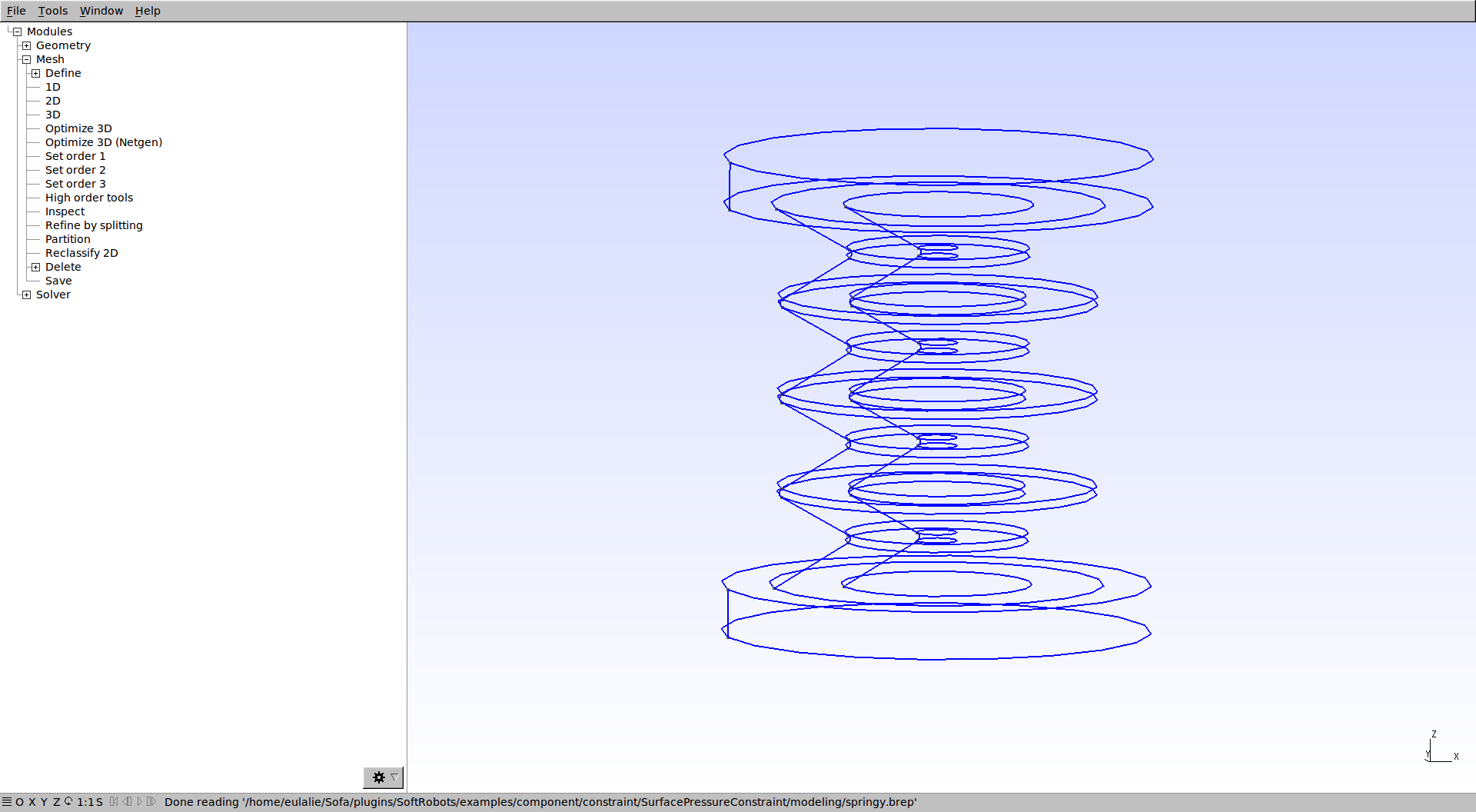
To generate a 2D mesh and a 3D mesh adapted to simulation, we propose to use GMSH. Using FreeCAD, export your mesh in “.brep” format. Load the “.brep” file in GMSH.
2. Options
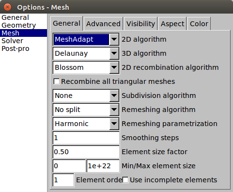
Several options are available to optimize your mesh. We recommend to use the “MeshAdapt” algorithm for the 2D generation. You can change the size of the elements (Element size factor) to get fine or coarse meshes.
3. 2D and 3D mesh generation
To generate your surfacic 2D mesh simply clic on “Modules/Mesh/2D”. See the following results.
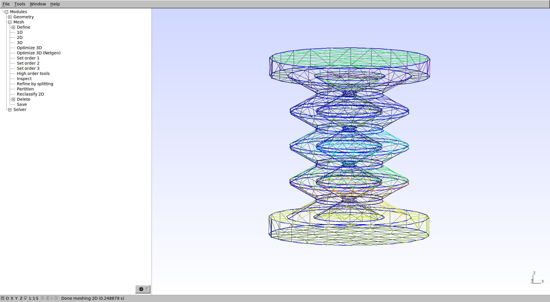
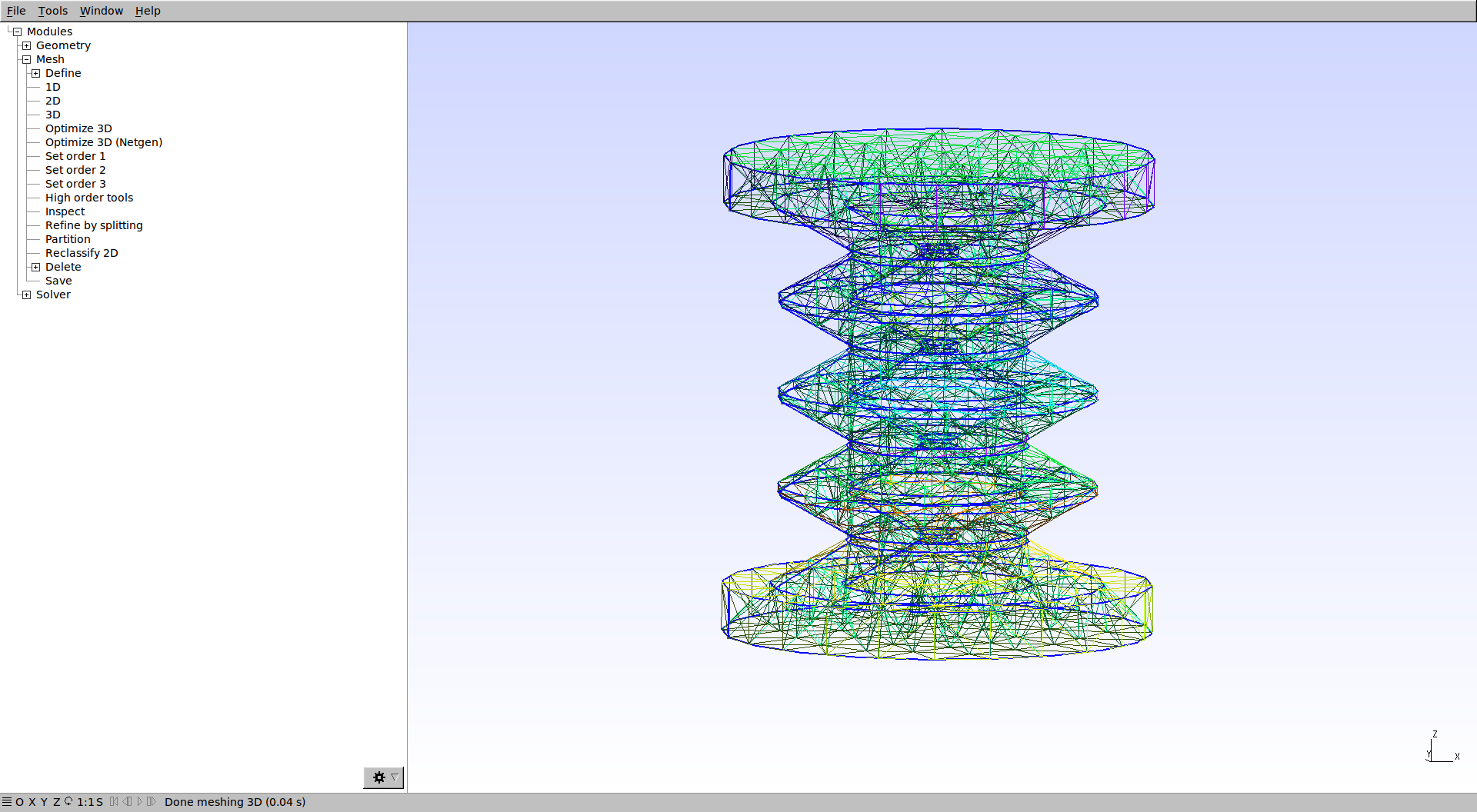
To generate the volumetric 3D mesh clic on “Modules/Mesh/3D”. See the following results.
4. Visualisation in SOFA
You can now follow the steps provided in “SoftRobots/doc/tutorials/Pneunet-Gripper” to load your mesh into SOFA and simulate pressure actuation.